I did extensive tests with toroids and r-cores and these are more silent (less hum) they produce much clearer and extended highs and naturally that also results in better resolution in the lower octaves.
Toroids have subjectively more present bass but with less detail and extension.
Done the same tests ages ago. The winners for sound were of course the EI lams, but quality between EI transformers varies a lot, so this cannot be a blanket recommendation.
The R-cores simply lack bass and dynamics, while being clean, extended and inoffensive in presentation. It is the closest a transformer can get to providing a politically correct sound. Cannot stand them in analogue circuits.
Perhaps we hear the same, but our interpretation differs a bit.
You may use 9530 or 9630
I found IRF9530 as per BoM. Thanks again!
UBIB1.3 > Allo Volt Plus amp.
Hi Salas.
First off, thank you for this very easy to build and implement baby!
I have put a second, the first one was meant to succesfully feed a litlle PianoDac+, 1.3 (19Volts) together to power a Allo Volt Plus (TPA3118).
It never sounded so fantastic! I use it dominantly for low-level listening in the small hours...
I feel that a shunt supply is not the ideal solution for an amplifier, since the power demand range is very wide of course.
This TPA3118 amp draws about 80 mA on its lowest setting, and I think 4-to-500mA on the highest setting.(listening level)
This means, I am affraid, that it is not possible to choose for an ideal shunt setting
I have choosen for 400mA total current, just for experimenting and it sounds amazing to my taste!
I understand I have to use 80+150=230 total CC for lowest level listening and 500+150=650 total CC for loudest listening-level? You teach us it is not a good thing useing a shunt setting that exceeds 150.....
A solution for me seems making R1 chooseable with a switch between f.i. 1 Ohm and 2 Ohm?
Maybe you have a better way?
Thank you in advance, Ed.
Last edited:
There could be noise implications with wiring a remote switch for that. Try with R1 1Ω and R9 1kΩ first to keep it idling for high level but make sure the sinking will be up to the task when the load shares low.
Thank you Salas!
I will give it a try. You wrote it already in the manual, did not pick it up!
Thanks for the nightly answer and have a good sleep!
Regards,
Ed
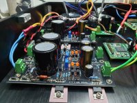
Need some help here, I had gone to tidy up UBiB my earlier DCG3 project.
All is good except one of the negative shunts which is outputting -22V7 no matter how I turn the trimmer. I tried to solder reflow to make sure there are no dry joints on the caps and M1/M2. The latter do not seem to be functioning given they are cold to touch.
Any advice?
All is good except one of the negative shunts which is outputting -22V7 no matter how I turn the trimmer. I tried to solder reflow to make sure there are no dry joints on the caps and M1/M2. The latter do not seem to be functioning given they are cold to touch.
Any advice?
I redrilled the holes to ensure that they are more reliable as the previous job wasnt satisfactory, strange thing is it just died. Of course I checked for non-continuity on the MOSFET tabs before powering anything up.What happened? Insulation problem?
No, they are populated components and was working till I decided to rework the chassis mounting.BTW double check their print not to have installed wrong M1 M2 types in this negative section
Has anyone successfully built a +5V 2.2A version suitable for an RPi?
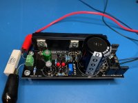
I have put one together using R1 with 0R27 7W, M1 IRF9640, M2 IRF640 and R9 with 1K5. It seems to work but M1, M2 and the rectifier diodes get very hot very quickly, and I seem to have smoked Rf (0R33 1W part supplied in the mini kit).
Should I have uprated Rf?
Also, what is the acceptable heat range for M1, M2 and the diodes? The spec sheet seems to say 150C but this seems quite high.
Any thoughts?
Attachments
M2 power at 5V should be low quite low, M1 depends on input voltage, let's say 12V: 7V drop *2.2=more than 15W! For a heatsink temp rise of 20°C above room temp you need something like that: SK58-100-SA | Heatsink, 1.3K/W, 100 x 150 x 27mm | RS Components. You want your UltraBiB reliable so you want good heatsink as other parts can't stand (think caps) the heat. Tiny heatsink on rectifiers' package are cheap.
I hope I'm right else I may fry next build!
I hope I'm right else I may fry next build!
Last edited:
- Home
- Amplifiers
- Power Supplies
- Salas SSLV1.3 UltraBiB shunt regulator

