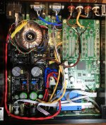
... So maybe the best I can do is just leave it as is? I'm a computer science person but I can imagine that my proposed seam treatment probably neglects certain laws of nature. Could it still help though to have something outside the rectangular transformer? May have space for a (unevenly curved) circular shield as well. Thank you!
https://belfuse.com/resources/white...-ST-Controlling-EMI-in-Power-Transformers.pdf
Fascinating little read! It does say that I should use a larger transformer and put it as far away from everything else as possible, but I'm not sure what it says about external shielding in particular... Is my case hopeless?...
You can't properly remake in complete close to core shielding an already plastic boxed transformer
I wasn't planning on taking it apart - just an extra band on the outside. Would that be superfluous?...
Cool. I have very poor judgement on this topic it appears...
But great to have expert opinion!Btw, the mumetal vendor told me I should make the closed band and then give it to them for heat-treatment... But since I can't really weld at home, and solder is probably not going to hold in 1000C, I'll probably just get a pre-treated strip and use it as is, if that doesn't sound crazy... Looking forward to putting things together!
Hi
I have just ordered the UltraBiB at the #2 GB and can't wait to receive the board
I am to install the board in a metal enclosure. Right now the metal enclosure is grounded to the 230v AC power socket.
Would you install the UltraBiB at metal-standoff's and then share the ground with the enclosure of isolate the board by using plastic standoff instead? Then wire the ground of the 3 x UltraBiB...
The UltraBiB is to power a DAC and Analog stage and right now I have not grounded the output RCA connectors to the enclosure.
Thanks
The rings at the mounting points are isolated to the ground planes. Each of the three reg sections is also completely independent. So there is no obstruction to adopt any system grounding scheme in various applications. What that scheme will be is a matter of the main circuits requirements.
Thanks for your reply Salas
I am to use -/+ 15 for my analog stage and the 5v for a i2s isolator (the clean side) and reclocker. That signal is fed from isolator->reclocker->DAC->Analog stage(I/V). Would you ground the ultraBibs together and then leave off the ground in the chain of i2s signal? Just to prevent ground loop...
The DAC is fed by a dual PSU from Twisted Pear Audio based on LM317. Would grounding the TPA PSU with the UltraBiB introduce noise?
Thanks again
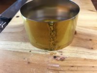
Yes its safe to eat a bit there
Great! Will post back soon after I fine-tune the VRR. Thanks a lot!
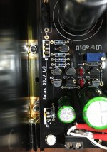
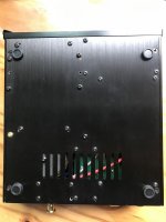
Expanded the holes and moved the PCB instead of shaving off the board and things managed to fit! Adjusted to 9V and Soekris sounds lovely
Still making final adjustments to the chassis, and have yet to install the mumetal shielding (0.3mm strip actually feels hard to bend, fully heat-treated one is still in the works and should be softer). Will post some pics soon.
Still making final adjustments to the chassis, and have yet to install the mumetal shielding (0.3mm strip actually feels hard to bend, fully heat-treated one is still in the works and should be softer). Will post some pics soon.
Last edited:
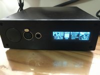
I always spend too long on final assembly. The build is incredibly compact - virtually no space between the components, and only a few millimeters from C1 to the top cover. Probably breeding ground for trouble but looks quite nice at least... The heat-treated mu-metal strip is still processing and I won't have it till next month. I'll probably stick to the one already installed for a while - the difference is likely negligible. Hopefully I didn't make any obvious mistakes!
Attachments
- Home
- Amplifiers
- Power Supplies
- Salas SSLV1.3 UltraBiB shunt regulator