I just looked at the manual and I did not pay attention to the mentions on the ESR. HI!
I think a Nichicon KA in 50V should agree (EX: 100uF).
https://hfc-fs.s3-eu-west-1.amazonaws.com/s3fs-public/nichicon_ka_datasheet_0.pdf
Does not specifically state other than loss and ripple. Try it and see if it will be stable with it.
Hello Salas
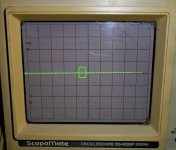
I tried to perform measurements as you recommend with the settings above but I have no change on the trace of the oscilloscope and the voltage of the UltraBib is very stable.
I took a picture of the trace on my old oscilloscope that I recovered recently and note that I am not familiar with the use of this device.
In the photo I surrounded in green the small setback that I also before the measurements and nothing changes when I test the positive or the negative.
")
I tried to perform measurements as you recommend with the settings above but I have no change on the trace of the oscilloscope and the voltage of the UltraBib is very stable.
I took a picture of the trace on my old oscilloscope that I recovered recently and note that I am not familiar with the use of this device.
In the photo I surrounded in green the small setback that I also before the measurements and nothing changes when I test the positive or the negative.
Attachments
Yes I will try with a Nichicon KA and familiarize myself a bit with the oscilloscope.
It's a shame this mistake of having put this capacitor of the transistor too close and which forces to use a 105° but I started to redraw my layout and now C3 is much more distant, the goal being to stay in dimensions of 10cm x 10cm.
Note that this arrangement with the heatsinks on the PCB is certainly valid for a current of 200mA (see 300 with heatsinks higher). Currently 2X12V and 200mA my little sink 4cm high seem sufficient. For higher currents and voltages the transistors will have to be positioned flat as for the official layout.
Salas,
My sincere thanks for the constant help!
After some problems in building the -12v BIB and the + 5V instability ... I got it all OK.
I honestly do not know what I did or what component could be wrong but in the matter of the +5v card the 1K in the R9 position made the difference for me.
I will keep a few more days out of the box before testing the oscilloscope.
For now ... from what I hear from dam 1021, still the "burn" I am very satisfied!
Best regards,
My construction:
1. Toroidal 30VA 2x 0V-12V for + 12v BIB and -12v BIB (Dam1021)
2. Toroidal 30VA 2x 0V-9V to + 5V (raspeberry pi)
3. Toroidal 100VA 23.5V-0-23.5V for 2x + 24V (Nac 122x)
An externally hosted image should be here but it was not working when we last tested it.
An externally hosted image should be here but it was not working when we last tested it.

Yes I will try with a Nichicon KA and familiarize myself a bit with the oscilloscope.
It's a shame this mistake of having put this capacitor of the transistor too close and which forces to use a 105° but I started to redraw my layout and now C3 is much more distant, the goal being to stay in dimensions of 10cm x 10cm.
Note that this arrangement with the heatsinks on the PCB is certainly valid for a current of 200mA (see 300 with heatsinks higher). Currently 2X12V and 200mA my little sink 4cm high seem sufficient. For higher currents and voltages the transistors will have to be positioned flat as for the official layout.
If you will turn the Mosfets placement flat and sinking directly on the chassis you will need no modifications as it is. Only insulate each Mosfet well and check that with the DMM's continuity beeper. Since you burn relatively little constant current right now, just a chassis should suffice. Unless you're absolutely limited by dimensions down to floor level.
P.S. Your oscilloscope should be a rebranded Goldstar (now LG), not bad at all as decent vintage 20MHz scopes go. For an amateur's overview and demonstration video that may help you bit further familiarize with it watch: Goldstar OS-9020A oscilloscope (1994)
Salas,
My sincere thanks for the constant help!
After some problems in building the -12v BIB and the + 5V instability ... I got it all OK.
I honestly do not know what I did or what component could be wrong but in the matter of the +5v card the 1K in the R9 position made the difference for me.
I will keep a few more days out of the box before testing the oscilloscope.
For now ... from what I hear from dam 1021, still the "burn" I am very satisfied!
Best regards,
My construction:
1. Toroidal 30VA 2x 0V-12V for + 12v BIB and -12v BIB (Dam1021)
2. Toroidal 30VA 2x 0V-9V to + 5V (raspeberry pi)
3. Toroidal 100VA 23.5V-0-23.5V for 2x + 24V (Nac 122x)
Happy that you like it on the DAM DAC. R9 at 1k can help stability when the extra shunt current (spare current) is set for too much or there is some "strange" interaction with a particular load.
Here’s a photo of my dual mono UBiB v1.3 to power the DCG3. The music has excellent spatial and its sweet, I like it!Thank you Salas.
Looking very good. Nice that you also subjectively like it.
Now that I have finished the DCG3, I am going to start putting together the Soekris DAM 1121 with the UBiB v1.3 and the Tube-I-zator output stage buffer.
I see that the DAM 1121 current specs are:
VCC5D - 250mA (typical), 350 (max)
VCC5A - 20mA (typical), 50 (max)
VEE5A - 20mA (typical), 50 (max)
Should I still cater for the 100mA buffer when choosing the R1 values?
Also, any advantages to use MUR120 on D1,D2,D3,D4 for the VCC5A and VEE5A?
I see that the DAM 1121 current specs are:
VCC5D - 250mA (typical), 350 (max)
VCC5A - 20mA (typical), 50 (max)
VEE5A - 20mA (typical), 50 (max)
Should I still cater for the 100mA buffer when choosing the R1 values?
Also, any advantages to use MUR120 on D1,D2,D3,D4 for the VCC5A and VEE5A?
Now that I have finished the DCG3, I am going to start putting together the Soekris DAM 1121 with the UBiB v1.3 and the Tube-I-zator output stage buffer.
I see that the DAM 1121 current specs are:
VCC5D - 250mA (typical), 350 (max)
VCC5A - 20mA (typical), 50 (max)
VEE5A - 20mA (typical), 50 (max)
Should I still cater for the 100mA buffer when choosing the R1 values?
Also, any advantages to use MUR120 on D1,D2,D3,D4 for the VCC5A and VEE5A?
Always use at least 100mA spare shunt current estimation above any load's rated peak current consumption. Consider 150mA spare is bit better dynamically if you have the sinking while 200mA spare as ceiling for practical needs. When there is load consumption play in the spec like min-max figures and the spare can be high during min phases, use R9 1k to damp the system better. If in doubt of consumption figures measure the loads mA with a DMM in series between their power input and PSU when powered from a lab PSU or a typical supply like an SMPS brick and LM317s for each rail before you will set up Ubibs so not to go back replacing R1 values.
If you don't have a lab PSU or a its boring to make a test PSU then its maybe handier for you to pre-test the serving limit of various R1s on your actual applications. Start with conservative CC estimations. When the Ubib Leds fail to light up or occasionally blink it means that the CC limit for average load current is set low or its just set low for consumption peaks.
MUR 120s are speedier than TO-220 MSRF when you don't need much current and the 120s can take it (25nS vs 95nS). Not for more than 300mA CC I would say, constant current is not allowing for off duty cool down cycle, so keep the 120s bit clear from the board for air to can move around their bodies to cool them down, as you do for R1.
The MSRF TO-220s are soft recovery also so they have some extra theoretical merit beyond being bigger. Although with the Rf-C1 filter the rectification EMI differences can be brought down enough. When Rf is replaced with a wire link the MSRF could possibly show more of its merit vs noisier diodes or you may like speedier types best, but that's fine subjective stuff for you more curious guys to play with and decide. Not to mention that if you ask around some would have to suggest this and that favorite rectification diode type discovery that you "must absolutely try" for this and that DAC or preamp etc.
Thanks for all the information. I will not have the luxury of building the prototype PSU to determine the R1 values.
Let me research more this week.
If I feed 12v battery directly to R1 it gets hot within 2 seconds.
I used two red leds of unknown ratings could this be the cause?
A bad M1 or bad J1 Q1 could be the cause. In any case you need something like 100uF local decoupling for C1 if you haven't used the regular big C1 at all because of battery feed.
- Home
- Amplifiers
- Power Supplies
- Salas SSLV1.3 UltraBiB shunt regulator