I thought of the higher than standard max output voltage capability modifications for Greg
1. CRD diodes Semitec E-501 (100V 300mW 0.5mA current regulative diodes) instead of J1 J3. Soldered from drain pad to gate pad replacing those two PF5102. CRD's cathode goes to gate pad is the orientation. R4 & R8 may remain as they will be skipped out of circuit by that action anyway.
2. BC556C BC546C (and B) instead of BC560C BC550C for Q3s
3. 470R instead of 270R for R5 R6. 330R instead of 270R for R7
4. 50K VR1 330K VRR instead of 20K 75K respectively
The above modifications should allow for 5V to 65V adjustable Vout range. Or 5V to 50V if VRR is 100K. Watch the capacitors DCV spec regarding the new higher AC Tx secondaries and new higher Vout range, also remember that the M2 MOSFET will dissipate more as the output voltage goes higher.
")
Thanks, Instead of CRD in J1, J3, I have some 2SK373. Can I use it?
Initially i was planning to mount the MSRF860Gs to use the amp chassis as a heatsink, but given that I was using these regulators for DCG3, I decided to forego drilling holes and bolting them down.
The 860G material looks plastic but I could be wrong, do I need to insulate them as they touch the metal chassis? TIA.
The 860G material looks plastic but I could be wrong, do I need to insulate them as they touch the metal chassis? TIA.
indeed.
They are insulated, no need for isolation, etc.
Initially i was planning to mount the MSRF860Gs to use the amp chassis as a heatsink, but given that I was using these regulators for DCG3, I decided to forego drilling holes and bolting them down.
The 860G material looks plastic but I could be wrong, do I need to insulate them as they touch the metal chassis? TIA.
The G type comes in TO-220FP package. Fully isolated because encapsulated in special plastic. Can still transfer heat to sinks if needed without having to use any SilPad or Mica insulators. There is simply worse thermal transfer (more thermal resistance) than with the exposed metal tab regular type. In the majority of applications that you don't want to max out its power handling potential on sinks, the encapsulated type is most practical. No insulation bits and mistakes.
This is my first DIY PSU
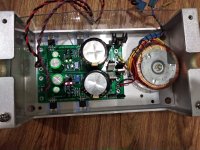
Finally,I complete the Ultrabib shunt regulator +-15V 350mA for my Opamp Katana DAC. The output Vcc driff about 0.5V from startup to stable state, and I will need put more heat shink. The sound quality improve, analog and clear that I can feel.
Many thanks for sharing, bravo Mr Salas !!!
Finally,I complete the Ultrabib shunt regulator +-15V 350mA for my Opamp Katana DAC. The output Vcc driff about 0.5V from startup to stable state, and I will need put more heat shink. The sound quality improve, analog and clear that I can feel.
Many thanks for sharing, bravo Mr Salas !!!
Attachments
Last edited:
Ran into some issues with the positive UBiB for DCG3. The voltage is stuck at circa 28V and I can't seem to adjust it using VR1.
Tried to reflow some of the solder points in case of dry joints. The other symptom is the 2 LED only light up momentarily whenever I tap on the board.
My 51ohm R2 is soldered on the back because the C1 obstructs.
Checked the JFET:
Q1,4 327-40
Q2,3 BC560C
Tried to reflow some of the solder points in case of dry joints. The other symptom is the 2 LED only light up momentarily whenever I tap on the board.
My 51ohm R2 is soldered on the back because the C1 obstructs.
Checked the JFET:
Q1,4 327-40
Q2,3 BC560C
First see if you really got constant current feed. Is there a near 0.6V voltage drop across the legs of R1? Also make sure you did not stuff a JFET in place of a BJT or vice versa. BJT names start with Q and JFET names with J on the board. Double check the MOSFET tabs insulation to the chassis with the DMM in Ohmmeter mode as well.

Hi Salas and guys,
I'm on the next batch of GB and already wonder stupid things, here they are...
Will some extra cap's legs length be a problem? (They will be laying on their side, 1U rack in sight). The larger the cap, the longer the bent legs... performance/stability problem?
Secondly, and I'm a bit ashamed of asking it, why no LED flush with PCB but almost always few millimetres up, held by these larger sections on the legs? Factory leftovers and annoying to remove? Cooling for limited drift?
Thanks!
- Home
- Amplifiers
- Power Supplies
- Salas SSLV1.3 UltraBiB shunt regulator