

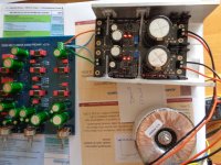
Here's a pic of my build of UltraBiB.
The transformer used has been specified for 18VAC+18VAC output, and I'm measuring about 17.6VAC with regs connected (CC=300mA). This should give me about 23.5VDC Vin across C1, but i' m actually measuring Vin about 21.2VDC.
Any ideas what causing this >2V drop?
Is it safe for 17VDC target output?
The transformer used has been specified for 18VAC+18VAC output, and I'm measuring about 17.6VAC with regs connected (CC=300mA). This should give me about 23.5VDC Vin across C1, but i' m actually measuring Vin about 21.2VDC.
Any ideas what causing this >2V drop?
Is it safe for 17VDC target output?
Attachments
How your mains measure? Your drops can only be the rectification's (two diodes Vf) and the EMI filter's drop across Rf. You may reduce Rf if it has high value or even replace it with a link if necessary. Else its drop is negligible. Or simply go drastic and reduce Vout to +/-15VDC still within the Douglas Self preamp's rail spec range.
It will still work sufficiently as it is set for 4.2VDC Vin-Vout difference producing less M1 heat. At 5-10V difference M1 would dissipate more to much more than now but it would also show several pF less Cgs (reacting faster).
It will still work sufficiently as it is set for 4.2VDC Vin-Vout difference producing less M1 heat. At 5-10V difference M1 would dissipate more to much more than now but it would also show several pF less Cgs (reacting faster).
Measure across the diodes and across Rf to see what happens. Maybe that particular transfo drops a lot under 600mA CC total? It does not look too small in the photo. How many VA it has on its label? For full bridge rectification in general the rated secondary current loses 40% or more spec vs middle tap or half wave.
Under 100mV drop at 300mA means using 0.33R Rf or bit less. Is that correct? If yes, your DMM is sane for mV scale. Check in your diodes datasheet the Vf drop vs current curve, spot Vf for your CC current point, then measure it across one diode's feet in the supply to see if it agrees. Tx VAC (loaded x1.41) - (2xVfreal+Rfdrop) must compute. Else something is amiss. Are those R1 combos in your photo two 1R in series by the way?
Yes, they are 2X1R 2W in series. The Rf is .33R and the diodes are MSRF860G both from the minikit.
The MSRF860G Vf vs If curve is not very descriptive for currents < 1A, but from the curves slope, I think it should be somewhere around 0.6-0.9V.
Worst case Vf=0.9V. So Tx VAC (loaded x1.41) - (2xVfreal+Rfdrop)=23V. and I' m getting about 21.2VDC. Strange
The MSRF860G Vf vs If curve is not very descriptive for currents < 1A, but from the curves slope, I think it should be somewhere around 0.6-0.9V.
Worst case Vf=0.9V. So Tx VAC (loaded x1.41) - (2xVfreal+Rfdrop)=23V. and I' m getting about 21.2VDC. Strange
21.2/17.6 = 1.2 ration - it can be if your transformer is fully loaded, but it isn't.The transformer used has been specified for 18VAC+18VAC output, and I'm measuring about 17.6VAC with regs connected (CC=300mA). This should give me about 23.5VDC Vin across C1, but i' m actually measuring Vin about 21.2VDC.
Any ideas what causing this >2V drop?
It means there is some things you don't see. (I havent seen the scheme now, so I cant say now more).
First thing that can make such a little strange behaviour - small measurement errors (real AC and DC voltage can be a little other value).
Voltage is quite low - I prefer to use Shottky diodes in such cases (40-50-60 V can be ok).
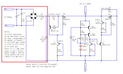
I see a scheme now - I see a resistor Rf before the first capasitor - it causes big voltale drop, because of big peak factor of cap current. To estimate this drop - we can multiply it by 3, I mean if load current is 0.3 A, and resistor is 0.5 Ohm, Voltage drop (caused by Rf) is about 0.3 A * 0.5 Ohm * 3 (peak factor) = 0.45 V.
Last edited:
He has Rf=0.33R. It still does not compute with his other numbers to forecast less than about 23V rectified i.e. a worst case ratio of 1.3 with his Tx measured VAC, type of diodes, use of Rf-C1 EMI filter, and 0.3A CC.
Yes, they are 2X1R 2W in series. The Rf is .33R and the diodes are MSRF860G both from the minikit.
The MSRF860G Vf vs If curve is not very descriptive for currents < 1A, but from the curves slope, I think it should be somewhere around 0.6-0.9V.
Worst case Vf=0.9V. So Tx VAC (loaded x1.41) - (2xVfreal+Rfdrop)=23V. and I' m getting about 21.2VDC. Strange
Vf for MSRF860G will be about 0.9 V (25C curve), because peak diode current is about 3 x 0.3 A = 0.9 A (round of 1 A). (They won't be very hot because of "small" load current compared to nominal 8 A diode current - about 6 % of nominal. Power dissipated by one diode is less than half Watt).
Rf=0.33R gives us V(Rf) = 0.33R x 0.3A x 3 (peak current) = 0.3 V peak drop.
R1 = 2R gives us V(R1) = 2R x 0.3A = 0.6 V drop (There isn't peak - it is after cap C1).
Rf=0.33R gives us V(Rf) = 0.33R x 0.3A x 3 (peak current) = 0.3 V peak drop.
R1 = 2R gives us V(R1) = 2R x 0.3A = 0.6 V drop (There isn't peak - it is after cap C1).
Last edited:
")
If sine is sine, than:
17.6V x 1.41 = 24.8V (peak voltage for ideal sine).
24.8V - V(Rf) - 2xVf = 24.8V-0.3V-2x0.9V = 22.7V.
He have 21.2V. It is about 7% error.
I think sine isn't sine (some %), and there is some multimeter measurement errors (about 1-2 %)...
17.6V x 1.41 = 24.8V (peak voltage for ideal sine).
24.8V - V(Rf) - 2xVf = 24.8V-0.3V-2x0.9V = 22.7V.
He have 21.2V. It is about 7% error.
I think sine isn't sine (some %), and there is some multimeter measurement errors (about 1-2 %)...
Last edited:
R1 will always drop about 0.6V no matter its resistance value because that's Q1's Vbe impressed upon it. R1 is the mA programing part of the constant current source limiter. The raw DC value to be considered as the rectification and EMI filter RMS result is on C1. Anyways, he has to measure the actual Vf in his build. His mains being somewhat clipped could be part of the explanation indeed.
- Home
- Amplifiers
- Power Supplies
- Salas SSLV1.3 UltraBiB shunt regulator