Salas, where/how do you “break” the closed loop to simulate the open loop?
Like this:
Attachments
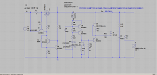
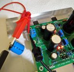
Since layout is critical when designing for line regulation, will have some boards made as close as possible resembling those illustrated in the first few pages of this thread.
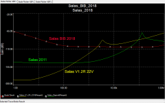
I compared three versions of the design, one dating from 2011, the other the V1.2R 22V, the last the schematic illustrated at the beginning of this thread. The PSRR of each vary in significant degree.
The 2011 version measured 131dB when tested, or about 10dB worse than the simulation. The Salas was a real champ when it came to PSRR in the Linear Audio bake-off.
Attachments
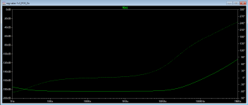
Yep, it was quite interesting how close your lab findings followed the simulation trends back then. This year's PSRR simulates like attached. The flat trend in audio frequencies is there, your attempt looks flat even in higher frequencies, about numbers I don't know what may be seen in the lab with real parts and boards practice. I will ask Tea-Bag to send you an original board on my expenses. Thanks for your contributions in measuring and for your interest.
Attachments
Attachments
It is evidently correct. Same method on the 2011 one that Jack measured close to sims in all areas. Also, according to your analysis my prototype would have behaved more or less like Selfy's when tested with his same load parts but it didn't (posts #54-59).
Different methods different parts different models differentiated circuit sections. We will not have a chance to match those analysis.
Different methods different parts different models differentiated circuit sections. We will not have a chance to match those analysis.
Thank you for pointing me out this great material but I think I passed the lesson about Tian's probe a long time ago.
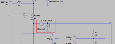
What about your decision to insert the probe - I do believe it is wrong. Just imagine where the NFB comes from and where it goes for. Of course there mustn't be any parallel loops.
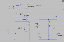
And if my initial drawing seems a little bit controversial to you, here's another one which will probably be more convenient.
Of course results are the same.
Attachments
Yes, I saw this but I'm stressing you again - look for the NFB and follow it.
The CCS does not participate in the global NFB so there's no any reason to separate the CCS section and the voltage regulation one.
The NFB is in the voltage regulation part - just observe it thoroughly.
The CCS does not participate in the global NFB so there's no any reason to separate the CCS section and the voltage regulation one.
The NFB is in the voltage regulation part - just observe it thoroughly.
Yes, you're right. It was too late and probably I haven't looked carefully at your schematic.I see its at the same place as yours. The CCS and the CFP output section are on a same line and between that line and the Vref etc. there's a probe.
That's why I decided to correct my schematic as close to yours as possible, see picture 1.
However, no matter what I've tried I wasn't able to achieve your results - 11 MHz ULG and 80 deg. PM. My results are shown on the picture 2.
I'm not sure what's the reason for such big inconsistency in the results that's why I'm also attaching the Spice file I used for simulation - may be someone will check it and decide if I'm right or not.
Attachments
Of course, thus rightly I couldn't see any difference in our probes placement. But no worries. Its the different drawing styles overall looks that perplexed you, but when looking again and thinking in nodes its clear. I don't have much time these days to go thoroughly through your analysis, but I will have a look at a point because its interesting to find causes. Maybe different semiconductor models (that you don't include). Anyways if I will manage to achieve analysis results approaching yours I will let you know the details. Others are welcome. In any case this line of regs goes several years back and the practical results are widely field tested. The new one is beta tested before introduced also.
By the way a general note. Guys, preferably don't put large electrolytics on an application's regulated rail if you can help it because they dominate any reg's output by imposing their own characteristics. Faster C0G etc. decoupling is more effective and elegant. Tantalums are also nice but they tend to short when they fail in the long run.
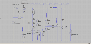
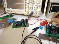
Here it is with 100Ω load and a 2200uF/25V BC cap hanging parallel on test leads. The reg not minding the silly situation at all merrily showing a flat line with the scope set at AC input 5mV/100uSec but to paraphrase a known sigline around here "Just because it can, doesn't mean you should"
Here it is with 100Ω load and a 2200uF/25V BC cap hanging parallel on test leads. The reg not minding the silly situation at all merrily showing a flat line with the scope set at AC input 5mV/100uSec but to paraphrase a known sigline around here "Just because it can, doesn't mean you should"
Attachments
Yes, the models are peculiar thing. I think I used the standard models which came with LTSpice but nevertheless, I'm attaching them here.
What about capacitors at the output of the regulator, I think we should create schematics which "feel better" when we attach a bigger capacitors at their outputs.
And ... the bigger, the better.
What about capacitors at the output of the regulator, I think we should create schematics which "feel better" when we attach a bigger capacitors at their outputs
.And ... the bigger, the better.
Attachments
I don't like big capacitors after very low wide flat Zo regs especially because its a shame they hijack the situation to their own spec. Sounding always heavy IMO. In the previous versions we had RC film cap Zobel termination option even just to avoid big chemical caps if we could. In this one such a minimal option can't be had but when we can keep the regulated rail as simple and light as possible in any config I am a fan of such an approach. The reg alone should be able to give the energy needed fast and even to absorb kicks in case its a shunt type. Each one to their own persuasion of course.
When Bode plots get you down, use "Z-Out" and look for "Q"
https://www.picotest.com/articles/A...essment of Voltage Regulator Phase Margin.pdf
Generally, use the lightest load possible.
https://www.picotest.com/articles/A...essment of Voltage Regulator Phase Margin.pdf
Generally, use the lightest load possible.
Hi Salas,
Would it be interesting to use a SMPS (for example laptop psu) rather than a transformer + rectifier + filter capacitor for this shunt regulator ?
I see several advantages:
- the cost
- the size
- the ease of deporting the PSU outside the case
- the ability to easily change input voltage for multiple applications
Will the results be as good ?
nounouchet
The results can be good and its a handy solution but some filtering after the SMPS may prove helpful.
Especially without the Rf+C1 RC filter the SMPS noise maybe it can propagate stronger past the M1 CCS barrier.
Such high frequency complex noises can couple easily enough on the layout and parts inductance anyway.
Depends on what SMPS. How noisy, what kHz its main ripple frequency.
In any case if you got a scope you may check if a specific one propagates any of its noise at the shunt's output or not, to see if you need take extra measures.
- Home
- Amplifiers
- Power Supplies
- Salas SSLV1.3 UltraBiB shunt regulator