Is the positive CC current enough for the job? Also try local 0V short wire joining at the regs outputs. Send single 0V line from there.
Hmm I think you maybe right on the positive board I am using a spare 12R 2W resistor on R1 but the negative I am using 3.3R 3W. Will try and see if I have another spare 3.3R 3W and use it on the positive board as well. After this will check if it still has some problem, then will try to connect the 0 of negative board to the 0 of positive board on the output side and then take a single wire from the positive 0 to the preamp line stage.
Thanks again Salas.
Planning Ultrabib supply for existing B1 Rev2 dc-coupled pre, currently running on laptop supply. Does anyone have suggestions concerning whether it's preferable to run a single +24v ultrabib through existing voltage splitter/virtual ground in B1R2, or to bypass the splitter with two +/-12v ultrabibs direct to buffer circuit? Thank you in advance for any advice!
Now I changed the R1 to 3.3R 3W and the positive board is working perfectly without any drop in voltage or switching off")
Thank you Salas again

Not sure if this should be on the group buy page ...
I got three of TEA BAGS kits. I had made mention that all of these would be 5 volts regulators when I ordered.
I finally am getting around to assembling them and find I have three different selections of leds.
One bag had both red and green, another only red and the last, only green. I doubt it matters but not all of the leds have the same casing.
Please tell me which ones to use, red or green. I know that red is what is specified. Not sure if the greens are best for 5 volts. I attempted searches but got nowhere.
They are to used with a Soekris dac so one will be much higher current than the other two.
Hope this isn't another one of those questions that has been answered twenty seven times previously.
Thanks,
Not sure if this should be on the group buy page ...
I got three of TEA BAGS kits. I had made mention that all of these would be 5 volts regulators when I ordered.
I finally am getting around to assembling them and find I have three different selections of leds.
One bag had both red and green, another only red and the last, only green. I doubt it matters but not all of the leds have the same casing.
Please tell me which ones to use, red or green. I know that red is what is specified. Not sure if the greens are best for 5 volts. I attempted searches but got nowhere.
They are to used with a Soekris dac so one will be much higher current than the other two.
Hope this isn't another one of those questions that has been answered twenty seven times previously.
Thanks,
Hi Rick,
They should be all red LEDS for 5v operation. So some earlier kits I included both. I have sense moved on to only red leds in kits that use a larger looking 'bulb'
Somewhere down the line I also changed the style of the LED as the one I used to use by Kingbright was end of lifed.
If I owe you some LEDS let me know, I will send them.
In each kit for 5V, or in a separate bag, their should be a labeled PF5102 JFET measured that is <7.5ma. If you are missing something send me a private message and we can get it figured out.
I haven't tried B1 Rev2 but if I was in your shoes I would start with a single positive UBiB supply to judge if there will be some satisfactory subjective upgrade first. Maybe somebody else has hands on experience to contribute.
Thank you, Salas. Do others have experience using Ubib with B1 (not mesmerize version) or B1R2?
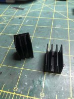
No, they are small. Better use the chassis for sinking. But insulate the Mosfet tabs.
Thanks, Salas
Is it correct that shorting VRR and VR1 will give a 5V output?
And it is recommended to use VRR with VR1 even though VR1 could well be a short?
I guess if VR1 fails VRR will be there to limit the voltage, though depending on application it could still be well over the limit .
And it is recommended to use VRR with VR1 even though VR1 could well be a short?
I guess if VR1 fails VRR will be there to limit the voltage, though depending on application it could still be well over the limit .
If VRR//VR1 will be bypassed with a wire, It will give little under 5V with red Leds. 4.7V or thereabouts depending on parts Idss & Vf tolerances. Usually little VR1 value is still needed for 5V. Can be even measured and replaced with a resistor. No moving parts no failure in the long term if critical to eliminate mechanical chances. There's no electrical stress on VR1 at so low Vout. VRR would be superfluous in this case.
VRR is there to limit VR1's upper adjust reach & share some of its dissipation in high Vout applications. Can be used as a handy place for a Zener also in a sans VR1 fixed voltage active Vref modification scenario.
VRR is there to limit VR1's upper adjust reach & share some of its dissipation in high Vout applications. Can be used as a handy place for a Zener also in a sans VR1 fixed voltage active Vref modification scenario.
A question for Salas: Will the PSU give a consistent output based on the total value of VRR/VR1? The reason I ask is that I will build 8 x 25v versions (4 +ve, 4 -Ve). On my first -ve version the total impedance for VRR/VR1 is 8.72K (this gives a very stable -25V). Will 8.72k give the same voltage approximately on all negative regulators or do tolerances play a part and I actually need to install VRR and measure the total resistance in each and every case. Just wanted to save time and soldering! I'm not interested in half a volt or so difference, but if I'm likely to get wide variations then I will build all of them and measure total resistance.
Last edited:
Q2s Vbe and J2s IDSS must be the same in all repetitions to expect exactly the same voltage drop result on same Vref resistance.
Repeating parts blindly will not lead to wide variations though. Because Vbe is the arbitrator. Which maybe its not the same between transistors working at relatively close Ic (determined by J2 & R7) but it does not vary widely either. The LEDS are consistent enough also. Especially the particular ones recommended.
VR1s are there not only to give a wide Vout adjust range but to take care of small differences between multiple regs also. If you want to use one experimentally calculated resistor instead of VRR//VR1 though, the first clone reg will show you enough about tolerance so to decide if acceptable and how to go on building the rest.
- Home
- Amplifiers
- Power Supplies
- Salas SSLV1.3 UltraBiB shunt regulator