Even on startup? Less than 500ma?That's the way Archphile, my distro of choice, is set up to run by default.
Such a configuration has very low power consumption, definitely less than 500mA.
Hello Salas,
Is possible to measure the rpi3 headless with hdmi disable, no screen, mouse , keyboard, and wifi?
Only ethernet...
I use it as a music player like that with volumio, or picoreplayer or max2play . I use a nas or pc to store music files.
Tks.
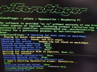
I downloaded and burned on mini SD card this image from your list of players to test. I use Foobar on W10 mini PC myself. I don't know how to go about this cruel RPI decapitation stuff

Attachments
Salas, sorry for the slight offtopic, but could you please post a link to the L-Adapter schematic?
Not proof finished yet. When it will work well on its own power source and PCB, it will also get its own thread with full info.
That's the way Archphile, my distro of choice, is set up to run by default.
Such a configuration has very low power consumption, definitely less than 500mA.
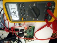
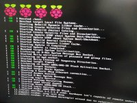
OK I also burned that one's image and run it. 522mA max (moments) and 212mA average during boot. Then it turns the HDMI off, the green lights don't blink anymore, and it pulls 217mA steadily.
Attachments
Hi,
I've built the +- ultraregs for 15V and they are running fine.
Built up a +V ultrareg for 5V.
These are tea-bags pcbs & kits. The +5V kit came with PF5102
jfets marked as 8.9 4.4 9.0 .
For the J3 position I used the 4.4 jfet.
Powered up the pcb with a 9volt xfmr and no load on the output
and the output voltage is 12+ volts and cannot be adjusted with
the pot.
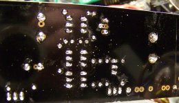
Any suggestions as to what I can check for, all solder joints look
good and none bridged. I need to verify resistor positions and
values, all resistors were metered before installing.
Thanks Ichi-
I've built the +- ultraregs for 15V and they are running fine.
Built up a +V ultrareg for 5V.
These are tea-bags pcbs & kits. The +5V kit came with PF5102
jfets marked as 8.9 4.4 9.0 .
For the J3 position I used the 4.4 jfet.
Powered up the pcb with a 9volt xfmr and no load on the output
and the output voltage is 12+ volts and cannot be adjusted with
the pot.
Any suggestions as to what I can check for, all solder joints look
good and none bridged. I need to verify resistor positions and
values, all resistors were metered before installing.
Thanks Ichi-
Attachments
I would rather first verify Mosfet tabs insulation to the sink with the continuity buzzer
Thanks, I'm on it! Be back soon!
Then Q2 & Q3's Vbe. Circa 0.61V each would be healthy. By the way when having a 20k voltage trimmer (VR1) it may take quite many turns before it will respond for lowish settings. Since that value is to cover a large 5V-40V output range, and as it comes midway set from the factory, it should be trying for about 25V in this circuit.
Then Q2 & Q3's Vbe. Circa 0.61V each would be healthy. By the way when having a 20k voltage trimmer (VR1) it may take quite many turns before it will respond for lowish settings. Since that value is to cover a large 5V-40V output range, and as it comes midway set from the factory, it should be trying for about 25V in this circuit.
No shorts of tabs to HS.
Will check Vbe s .
On the pot I ran it all the way up & back, with no voltage variation.
M1 & M2 are not mistakenly mixed for types, right?
M2 is irf530
M1 is fqp3p20
Then Q2 & Q3's Vbe. Circa 0.61V each would be healthy.
.03V for vbe on q3
.27V for vbe on q2

- Home
- Amplifiers
- Power Supplies
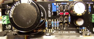
- Salas SSLV1.3 UltraBiB shunt regulator