The stability problem with mine version could easily be the modified CSS part of the regulator.
In my implementation there are no source resistors for the 2SK880s. I use them only for simulation purposes (Idds).
I am tempted to try a diode (1N4148) in place of R9, once I figure out the reason for the instability.
In my implementation there are no source resistors for the 2SK880s. I use them only for simulation purposes (Idds).
I am tempted to try a diode (1N4148) in place of R9, once I figure out the reason for the instability.
Attachments
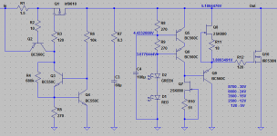
You are treading away from the original's parts choices along with playing on different layout so many scenarios are possible on why it behaves differently. Sticking to the 1.3 basic architecture alone isn't a guarantee its a proper 1.3. If it was your CCS mod it would be spewing AC packets all the time but you only found them when playing with the load type. Replace the FM C3 with an FC at least.
salas could you please tell me what toroidal transformer you recommend for 1.3?
is this fine?
AS-1230 - 100VA 30V Transformer - AnTek Products Corp
is this fine?
AS-1230 - 100VA 30V Transformer - AnTek Products Corp
As a matter of fact I built one early prototype to test it on the Soekris that DimDim had loaned to me for an extended period during my Aune S16 had to be factory serviced so I know first hand on that one. You need a 12-0-12 Vac 50VA transformer. You should also use a 2.2R 2W R1 on positive section's CCS/current limiter and a 3.3R 2W R1 on the negative section. Those are setting 270mA CCS on the positive and 180mA on the negative for a balanced spare current result since the Soekris draws less current from the negative side. I set the reg for +/-9 Vdc out on DimDim's recommendation.
thank you so much. so this one:
AN-0512 - 50VA 12V Transformer - AnTek Products Corp
AN-0512 - 50VA 12V Transformer - AnTek Products Corp
As a matter of fact I built one early prototype to test it on the Soekris that DimDim had loaned to me for an extended period during my Aune S16 had to be factory serviced so I know first hand on that one. You need a 12-0-12 Vac 50VA transformer. You should also use a 2.2R 2W R1 on positive section's CCS/current limiter and a 3.3R 2W R1 on the negative section. Those are setting 270mA CCS on the positive and 180mA on the negative for a balanced spare current result since the Soekris draws less current from the negative side. I set the reg for +/-9 Vdc out on DimDim's recommendation.
One note on this - my dam1021 has its bridge rectifier removed and bypassed.. On non-modded DAMs input voltage should be about 9+1.4=10.4V to be equivalent to what we were doing.
i dont underatand. on antek website there is 9v and there is 12 v but no 10v. also can i go above 50va? like 100va?
Transformers - 100VA - Page 1 - AnTek Products Corp
Transformers - 100VA - Page 1 - AnTek Products Corp
i dont underatand. on antek website there is 9v and there is 12 v but no 10v. also can i go above 50va? like 100va?
Transformers - 100VA - Page 1 - AnTek Products Corp
I believe he meant to set the reg at 10.4Vdc output for a non modified DAM unlike his. But he will clarify further I guess. Not talking about the transformer's AC spec. That one remains 12-0-12 Vac. You can go above 50VA since those AnTek are magnetically shielded so an oversized core will not also throw around too wide a magnetic field.
ok i think that i underatand now. i tend to stick to the higher limits on the specified voltage usually of course never going above. so instead of 9v i think i will go with 12 volts from the trans. so i will get the 100VA 12 volt
AS-1212 - 100VA 12V Transformer - AnTek Products Corp
AS-1212 - 100VA 12V Transformer - AnTek Products Corp
I have the Ref-D design around low threshold. Diodes have tempco and some noise also so I don't know its full impact off hand. The less the impedance there the less effective the cap's filtering. Output contacts and cabling will swamp Zo differences at some practical value. For 5V its also alright as it is. If we will try to make this reg extend even lower at a point it surely has the parts positions for experiments already.
- Home
- Amplifiers
- Power Supplies
- Salas SSLV1.3 UltraBiB shunt regulator