Just after the active bridge, I am using CLC (15000uF /33mH/15000uF) then Ubib to power the Aca. R1 in Ubib is 0,288 ohm (0,3R parallel 7R3).
I like active bridge, is an increase in bass and treble extension, dynamics, detail, only a slight downside, sound is less smooth than using Cree Sic diodes. But my opinion, the coldness on active bridge, is related to their transparency, showing the limitations of mediocre passive parts present in the circuitery.
Merlin and I, we both have set AC phase right to IN1 (pin 8 ic LT4320).
Jordi
Metal film regulars will do fine also. Do calculate 0.6V times CCS current in each case to find expected dissipation of R1. That will let you expand choice of nominal wattage R1 to parts with no less than three times the actual dissipation. For example when projecting 1A CCS setting it will be 0.6W actual R1 dissipation. Thus as a rule of thumb don't use less than 2W part (0.6W*3=1.8W) to avoid hot and to expand long term reliability. Five times will ensure rather cool i.e. 3W R1 nominal part choice. Resistors get hot below their power rating which represents nearing a breaking point not just a hot to the touch point.
With the above example its understood that for smaller CCS settings you may find many resistors choices in the 1W range suitable. Case by case CCS setting R1 dissipation examination widens choice beyond the general worst case based guidelines of the PDF guide.
With the above example its understood that for smaller CCS settings you may find many resistors choices in the 1W range suitable. Case by case CCS setting R1 dissipation examination widens choice beyond the general worst case based guidelines of the PDF guide.
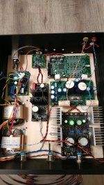
Hi guys, so the time has come and I finally finished my dam1021 based dac with B1 with Korg triode as output buffer. I chose to feed the dam board and the USB input chip with our Salas' regs, the Ultra Bib and the Reflektor-D. It seems to work really fine, sounds appears very nice, surely better than the previous TEAC UD-301, which still remains a respectable device for its cost. There is only one thing that annoys me a bit: when I turn the preamp volume knob to maximum, there is a clearly udible hum which disappears when I turn off the dac section, while keeping the buffer section turned on. I have to say that transformers are a bit noisy, the classic mains noise. May this noise pass through the regs (I don't know which one, may be the Ultra Bib or the Ref-D) and end in the output signal? Is there something I could do to get rid of this noise?
Thanks to everybody and in particular to Salas, which was really patient in answering to all my silly questions.
Gaetano.
Thanks to everybody and in particular to Salas, which was really patient in answering to all my silly questions.
Gaetano.

Very nice build. The noise you describe should be either interference or a low level ground loop between digital and analog. Systematic approach would be to first spot it on a scope, FFT analyzer, meter, or use a cheap audio device monitor, something handy. So you can easily tell when its present or gone and start some experiments. With shielding and / or signal cabling - grounding, until reduced or eliminated. Starting from simple things. The easier to think of and try first.
For instance:
Maybe coaxial signal wire could do better? Is the box referring at signal ground also? Maybe it should with the use of a 10 ohm resistor. What about referring it at the power ground of the PSU(s) instead? Should there be grounded metal foil over the wooden bottom panel? What happens if you rotate a board or a large component? Anything changes if dressing the AC power wiring differently? Etc.
Hi Salas, I have already connected the trafos shield with the chassis and this to mains ground. I tried also to connect the signal ground to the chassis, but without any positive effect. I have to say that the signal ground comes from the B1 Nutube buffer, so not directly from the unbuffered output of dam1021. Instead, don't you think that a not good quality of trafos could introduce mechanical hum? Indeed trafos I used are not so quite, they are, as I said, noisy. I can clearly hear their hum when the device is on. Do you think that more silent trafos could solve the issue? E.g. a single good trafo with three secondaries?
Gaetano.
Gaetano.
Do those trafos mechanically hum when unloaded too? Maybe the particular ones are not so well made to keep up with the constant current load. Are your CCS settings hot rod? I don't know if changing the transformers is going to solve it for sure because when you shut down the DAC part, the max volume background noise goes out. In any case I recommend Talema and for custom wounded Toroidy if the transformers are mechanically weak. Those are accessible to Europeans.
Try power grounds to chassis also. One at a time. From points at the PSUs. Crocodile leads help for quick experiments.
Try power grounds to chassis also. One at a time. From points at the PSUs. Crocodile leads help for quick experiments.
Hi Salas, I don't know if there is the mechanical hum with unloaded trafos, I should try. As regards CCS settings, I have 1.8R and 2.7R respectively for positive and negative Ubib rails and 1.1R for Ref-D. Are they hot rod? Why do you think that changing trafos could be unuseful? Am I missing something? As you correctly wrote, the noise background disappears when I turn off the DAC section and this one is fed by the two trafos. So, in particular, when I turn off the trafos, the hum goes away. Therefore, I believe that this doesn't exclude them as the culprits of the noise. Am I wrong? Besides, can I consider that the buffer stage could catch some noise from the psu?
Gae.
Gae.
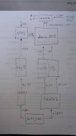
Not particularly hot rod. What do you mean its fed by the two trafos? What AC feeds the PSU for the Korg line level board? Is there a shared secondary between analog and digital PSUs? Can you provide a quick wiring diagram of what's in that box? Pen and paper and a mobile phone photo of the sketch are good enough tools for the purpose.
Two parallel fat diodes with opposite facing cathodes between mains earth wire and box. But you can just pull the mains ground wire for a quick test. If making a difference install it with the diodes. Safe lift.
By the way, the long transformer shield wires aren't effective for channeling away possible RF from the internal static shields. Due to their self inductance. Better shortened and bolted somewhere on a near chassis panel. Which must be showing continuity with the other panels. If not, scratch anodized or painted panels at inside corners where they meet.
By the way, the long transformer shield wires aren't effective for channeling away possible RF from the internal static shields. Due to their self inductance. Better shortened and bolted somewhere on a near chassis panel. Which must be showing continuity with the other panels. If not, scratch anodized or painted panels at inside corners where they meet.
- Home
- Amplifiers
- Power Supplies
- Salas SSLV1.3 UltraBiB shunt regulator
