Here is a photo of the setup. Thanks for the suggestion where to tap the +vdc for the LED power indicator.
Very nice. Tocos pot is nice too. Reminds of classic preamps boxing. D2 anode in the positive section should also be at GND potential for a shorter grey return wire if I remember correctly. Check that with the DMM for continuity. Twist grey with the red.
I checked the voltages on my board which I must add is not a GB one.
Initially I had 0.593 across R1; 5.38 vgs on M1 and 1.78vgs on M2. Thinking I had found the problem I changed M2 but whilst theboard was out I changed all the small transistors(wrong move). I now have 28 vgs on M1 and the same 1,7 vgs on M2.
Across R5-0.382V; R70.77V.
All resistors measure ok apart from R7 which is reading 53R; all measured in circuit.
Thank you. The trimmer did measure smoothly with my dmm across the 75k resistor. Is it possible for a fault to appear under voltage? I will remove Q2 and check it with the Peak and check again the board with a magnifying glass. Does the high vgs on M1 mean I have damaged it? Appreciate the help Nick.
As the BC56C is no longer manufactured would this be a suitable replacement;
https://uk.farnell.com/on-semicondu...https:en-GB/Element14_United_Kingdom/w/search
https://uk.farnell.com/on-semicondu...https:en-GB/Element14_United_Kingdom/w/search
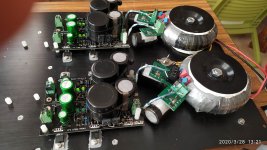
Completed Ubib power supply, all set at 17V. to power DCB3. It was one rail that need fix a cold solder point in one led. I splitted C1 by two identical 3300uf and big Mundorf AG+ 1000uF. Therefore I may have easy access for CRC or CLC in the future. Also bypassed diodes, upgraded to active bridge.
Attachments
Last edited:
Completed Ubib power supply, all set at 17V. to power DCB3. It was one rail that need fix a cold solder point in one led. I splitted C1 by two identical 3300uf and big Mundorf AG+ 1000uF. Therefore I may have easy access for CRC or CLC in the future. Also bypassed diodes, upgraded to active bridge.
Congrats. This much attention to the raw DC part can't go without some end benefit.
Salas, I had a few questions:
- Is the below a suitable replacement for MUR120 for D1-D4?
MUR120G ON Semiconductor | Mouser
- For C1, I assume no issue with using a 6800uF 63VDC Mundorf cap, as opposed to the 40VDC version.
- What size gauge wire do you recommend using between Ultrabib out and the circuit being powered? I believe I read in one thread 12-14 gauge, but this seems large and I think the power terminals usually only accept 16.
- Would you expect any benefit from using a 4 pole Mundorf MLytic AG+ on a DC flexy, housing the rectification in a separate chassis, and wiring the DC power to C1? Or would the benefits of the 4 pole cap be negated by the distance and splitting up the circuit?
-MUR120G is the same part yes.
-Absolutely no issue as long as it fits.
-Use max diameter wire the terminal nicely accepts. Also possible to opt for direct soldering in a done and dusted built.
-Rather negating, yes. Unless its about a high gain circuit sensitive for hum. There the complete separation would do good. Because of no AC wiring entering the main case whatsoever.
")
Question on substitutions for the parts that are becoming scare (PF5102 & BC560C)
For J1, J2, and J3 (PF5102)
Based on a LTSpice simulation, it looks like the goal is 2ma through these devices. Other than the J113 discussed earlier, is a 2ma CRD (such as the Semitec E-202) a viable option? Other than the CRD being more expensive than a J113 + resistor.
For Q2 & Q3 (BC560C)
Is BC559C a realistic substitute? Understanding that its 30V limit would reduce the available voltage output range.
- Home
- Amplifiers
- Power Supplies
- Salas SSLV1.3 UltraBiB shunt regulator