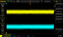
Hello. Probably my question is very newbie but I didn't find answer anywhere else. I've recently got my first oscilloscope and tried to measure output of my dual rail +/- 12V regulated power supply that I use for preamplifier that I'm building. Power supply is built on standard LM317/337 regulators. I've attached picture of what I see on oscilloscope and want to understand what it means.
As I understand I see around of 40mV of fluctuation (high frequency).
I don't really understand what it is ripple, noise or oscillation and if it's ok. Can you please help me with that?
As I understand I see around of 40mV of fluctuation (high frequency).
I don't really understand what it is ripple, noise or oscillation and if it's ok. Can you please help me with that?
Attachments
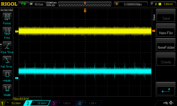
It might be your scope probe and its ground lead. To learn more, disconnect your probe from the power supply and instead use it to measure the voltage of a 1K resistor. Ground clip goes to one end of the resistor, scope probe goes to the other end of the resistor. Leave the vertical sensitivity at 20 mV per division. If your measurement apparatus were noise-free, we'd expect to see about 80 microvolts of thermal noise from a 1K resistor. But instead if you see the same 40 millivolts, yet it's not connected to a power supply at all, then you can be confident the 40mV is not coming from the LM317/LM337 ... it's coming from your measurement setup.
Conclusion: some, but perhaps not all, of the displayed noise originates from other sources that are NOT your voltage regulators.Tried with 1k resistor (metal film if it's important) and peak to peak signal with it is 16mV
MarcelvdG's suggestions are excellent, good luck!

I saw a study that recommended a load for three-pin regulators of 220uF, with ~100mΩ ESR; also 220uF across the voltage adjustment resistor. This provided the best noise and ripple characteristics. Also note that the Linear Technology LT317/337 regulators have definitely better datasheet specs than the typical T.I. LM317/337s----about 16db better ripple rejection and about 10db less noise. They're more expensive---about $2.50 each, while T.I.s are 50¢; but for DIY projects where you're only using a few, it's money well spent.
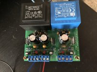
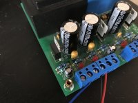
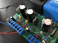
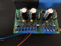
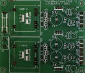
Input ceramic sits almost right on the input leg of regulator and output capacitor is around 1.5-2cm away from the output leg. Here are several photos of the PSU board.
Attachments
Last edited:
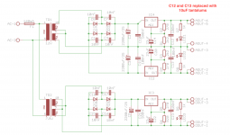
The distance from capacitor (PIN +) to PIN 3 of LM317 must be less than 1cm.
The same for PIN 2 (output PIN).
And you also add diodes (like 1N4001) from output to ground (anode to PIN 2)
And from output to input (anode to input (PIN3))
Have a look at the datasheet for that. Here: https://www.google.de/url?sa=t&rct=...nk/lm317.pdf&usg=AOvVaw1yBsSEjROPMAJjbmXwAgfV
The same for PIN 2 (output PIN).
And you also add diodes (like 1N4001) from output to ground (anode to PIN 2)
And from output to input (anode to input (PIN3))
Have a look at the datasheet for that. Here: https://www.google.de/url?sa=t&rct=...nk/lm317.pdf&usg=AOvVaw1yBsSEjROPMAJjbmXwAgfV
Last edited:
Tried with 1k resistor (metal film if it's important) and peak to peak signal with it is 16mV
Did you measured free-standing 1k resistor (not connected to this PSU)?
This is far more than predicted 80uV Johnson noise
") few posts above. Perhaps an osciloscope issue?
few posts above. Perhaps an osciloscope issue?- Status
- This old topic is closed. If you want to reopen this topic, contact a moderator using the "Report Post" button.
- Home
- Amplifiers
- Power Supplies
- LM317/337 ripple/noise/oscillation