Sometime ago, I needed a >60V >5A supply for some tests, but realized with some surprise that none among my tens (including those in the attic) of lab supplies could fit the bill.
I could easily have used parallel or series combinations of existing supplies, but that's a practice I have carefully learned to avoid: even well-protected supplies are intended to be used in one quadrant, perhaps one and a half at most, but when things go seriously wrong in combinations, the weakest link can be subjected to a variety of stresses vastly exceeding that, starting a "chain reaction".
Rather than the quick and risky option, I opted for the sensible solution: cover that I-V segment with one more lab supply.
As it doesn't need to be refined, accurate or offer the best performances, and I had all the important parts, I opted for a conventional 50Hz transformer input, followed by a buck converter.
Initially, I had considered a SCR regulator, like many of the workhorses of 60's or '70s: HP, Fontaine or Sodilec for example.
The problem with SCR regulators is the huge level of perturbations sent to the mains by the phase control, and the big inductors required to make the current spikes less unacceptable.
In the end, I opted for a buck regulator, also a ghost from the seventies, but somewhat less primitive, and having the interesting feature of current boosting at low output voltages.
The transformer I used is a monster, probably from a tube color TV, that I rewound decades ago as a teenager, with the intention of using it in a multichannel sound system.
By the time it was finsished, single supply amplifiers were completely out of fashion, meaning it has been gathering dust since then.
This project was at last an opportunity to use it. It is an awful piece of crap iron, in the style of MOT's, and the magnetizing current alone is more than 700mA. The laminations are probably repurposed tin plates....
Anyway, awful as it is, it does its transformer job, and delivers 50V @ 750VA.
Because of the lowish 50V, I used a voltage doubler rectifier.
The caps (a total of 7700µF/polarity) are minimal for such a power level, but the positive aspect is a good power factor, and the resulting huge ripple is easily polished off by the buck regulator.
The structure I adopted for the regulator makes it universal, adaptable to other current or voltage ratings with the change of just a few resistor values.
It comprises a switching block, referenced to the negative rail, and a regulating block referenced to the positive rail.
The communication is via a current-mode PWM signal.
No auxiliary supplies or similar impediments are required, and the scheme can be used for input voltages from ~35 to ~350V.
To be continued....
Attachments
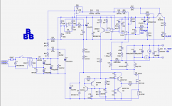
The voltage-doubler rectifier is not the most effective of solutions, but as I wanted to use this transformer, it was the only possible option (I wanted to reach >100V output).
The supplies of the two control blocks are shunt regulators, fed from the main DC input via a common limiting resistor R20+R21.
This solution wastes some power, but compared to an auxiliary transformer, it is simple, reliable and kills two birds with one stone.
The PWM oscillator is built around U1A and operates at a frequency of 50kHz (not critical).
The reference signal for the PWM modulator is not the pure exponential sawtooth available on C8, but a composite of negative-going pulse and sawtooth (the reason behind this choice will be explained later).
U1B compares this waveform to the error signal from the regulator U2A.
This opamp compares the reference voltage from the potentiometer with a fraction of the output voltage, both referenced to the positive rail: bifet amplifiers like the TL082 include the positive rail in their common-mode range.
This fact is only informally documented in the applications and datasheets, because the performances are somewhat degraded, but the amplifier remains perfectly functional, which is sufficient.
Some series of bifet opamps have this feature explicitly advertised, but they are significantly more expensive.
U2B is the current limiter: it compares the voltage from a current shunt R2 to the ~930mV from the divider R31/R32.
When the input current approaches 5A, the output of U2B goes low, overriding the voltage regulation through the diodes D10-12.
Q6 detects the condition and lights the limitation LED.
This limiter is very slow, because its only purpose is to thermally protect the transformer from prolonged over-currents.
The PWM signal at the output of U1B is converted into current by Q1, and translated to the negative rail, where the gate buffer Q2/Q3 drives the MOSfet.
The source current is monitored by the shunt R14, and triggers an SCR-like circuit when a peak current of ~12A is exceeded.
Unlike the previous one, this limiter is very fast and operates at sub-period scales.
Because the synthetic SCR is not self-resetting, it is necessary to include a dead time in each cycle, otherwise one would have to disconnect the power and wait each time the protection has tripped. This is the reason for taking the PWM waveform at the output of U1A rather than from C8.
The transistors of the SCR need to be saturated-switching types, like the 2N3904/6, otherwise they remain conducting after the dead-time.
It may seem strange to have two different current limiters (and none user-controlled), but they fulfill very distinct roles: this one protects the MOSfet against high peak currents possible with the buck topology: when the output voltage is low, the output current (and thus the peak current) can be very high without consuming significant amounts of power.
The condition could therefore not be detected by the input limiter, and could damage the switching components: MOSfet, inductor and catch diode.
Both are thus necessary. If a user-controlled one had to be added, it would require a third circuit, but I chose not to implement one: the philosophy of the BBB is to provide raw power, and the nominal current is (loosely) set by the peak current limiter at around 10A, thanks to the buck operation: the short-circuit current is ~12A, and at 60V, the transition between the two limiting modes, it something like 9A, but that is not really important.
A user-controlled limit would be mostly futile: with the two 1,000µF output caps possibly charged at >100V, there is enough of energy available to fry any failing prototype....
The role of C14 and the saturable ferrite bead is to control the reverse-recovery spike of the catch diode: even though the BYW31 is quite fast, the current spike is significant if no precaution is taken.
Note that the circuit is capable of significantly higher currents than 10A: initially, it was dimensioned for 20A, but the dissipation (25~30W, essentially conduction losses) was unbearable for the smallish heatsink.
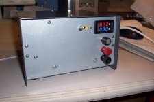
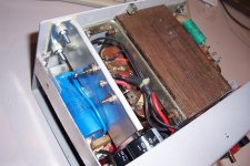
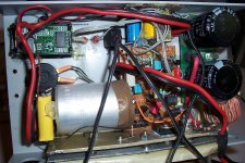
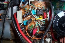
Here are some pics of my build:
The supplies of the two control blocks are shunt regulators, fed from the main DC input via a common limiting resistor R20+R21.
This solution wastes some power, but compared to an auxiliary transformer, it is simple, reliable and kills two birds with one stone.
The PWM oscillator is built around U1A and operates at a frequency of 50kHz (not critical).
The reference signal for the PWM modulator is not the pure exponential sawtooth available on C8, but a composite of negative-going pulse and sawtooth (the reason behind this choice will be explained later).
U1B compares this waveform to the error signal from the regulator U2A.
This opamp compares the reference voltage from the potentiometer with a fraction of the output voltage, both referenced to the positive rail: bifet amplifiers like the TL082 include the positive rail in their common-mode range.
This fact is only informally documented in the applications and datasheets, because the performances are somewhat degraded, but the amplifier remains perfectly functional, which is sufficient.
Some series of bifet opamps have this feature explicitly advertised, but they are significantly more expensive.
U2B is the current limiter: it compares the voltage from a current shunt R2 to the ~930mV from the divider R31/R32.
When the input current approaches 5A, the output of U2B goes low, overriding the voltage regulation through the diodes D10-12.
Q6 detects the condition and lights the limitation LED.
This limiter is very slow, because its only purpose is to thermally protect the transformer from prolonged over-currents.
The PWM signal at the output of U1B is converted into current by Q1, and translated to the negative rail, where the gate buffer Q2/Q3 drives the MOSfet.
The source current is monitored by the shunt R14, and triggers an SCR-like circuit when a peak current of ~12A is exceeded.
Unlike the previous one, this limiter is very fast and operates at sub-period scales.
Because the synthetic SCR is not self-resetting, it is necessary to include a dead time in each cycle, otherwise one would have to disconnect the power and wait each time the protection has tripped. This is the reason for taking the PWM waveform at the output of U1A rather than from C8.
The transistors of the SCR need to be saturated-switching types, like the 2N3904/6, otherwise they remain conducting after the dead-time.
It may seem strange to have two different current limiters (and none user-controlled), but they fulfill very distinct roles: this one protects the MOSfet against high peak currents possible with the buck topology: when the output voltage is low, the output current (and thus the peak current) can be very high without consuming significant amounts of power.
The condition could therefore not be detected by the input limiter, and could damage the switching components: MOSfet, inductor and catch diode.
Both are thus necessary. If a user-controlled one had to be added, it would require a third circuit, but I chose not to implement one: the philosophy of the BBB is to provide raw power, and the nominal current is (loosely) set by the peak current limiter at around 10A, thanks to the buck operation: the short-circuit current is ~12A, and at 60V, the transition between the two limiting modes, it something like 9A, but that is not really important.
A user-controlled limit would be mostly futile: with the two 1,000µF output caps possibly charged at >100V, there is enough of energy available to fry any failing prototype....
The role of C14 and the saturable ferrite bead is to control the reverse-recovery spike of the catch diode: even though the BYW31 is quite fast, the current spike is significant if no precaution is taken.
Note that the circuit is capable of significantly higher currents than 10A: initially, it was dimensioned for 20A, but the dissipation (25~30W, essentially conduction losses) was unbearable for the smallish heatsink.
Here are some pics of my build:
Attachments
- Status
- This old topic is closed. If you want to reopen this topic, contact a moderator using the "Report Post" button.