Appreciate your suggestion, am supplying fixed 32v from meanwell to this China-made amp; I would have difficulty supply this voltage on batt, in order to make comparison definite conclusive.... The simplest test for identifying if your preamp power supply is contributing noise/hiss that you can hear is to temporarily use a battery power supply for your preamp...
Appreciate sharing your much needed experience, wonderful suggestion!... The switching frequency of the Mean Well units tends to be around 70 kHz. You can attenuation that with a well-designed CLC filter. Make sure to limit peaking in the filter as that will boost the noise (due to the resulting higher supply impedance) rather than suppress it.
One way to determine whether your preamp or power amp is the dominant noise contributor is to use a shorting plug on the power amp. Short its input. Measure the output noise. Then connect the preamp with the volume turned all the way down (or a shorting plug on the selected input). Measure the output noise. If the noise increases significantly when you attach the preamp, the preamp is dominating (or at least contributes as much as the power amp to the noise level).
Tom
Got some ques. for you:
- this China-made amp, has both pre-amp NE5532 & Class D TPA3250 on the same PCB; doesn't shorting inputs of TPA3250 equivalent to shorting outputs of pre-amp NE5532 & result in damaging to pre-amp?
- does meanwell ripple noise will have any other impact to DAC's SQ, besides also introducing noise?
Here one example of noise results for smps used in preamp/headphone amp:
http://www.diyaudio.com/forums/head...headphone-amplifier-mo-3-a-7.html#post5289207
and info regarding smps usage in audio:
http://www.diyaudio.com/forums/pass-labs/316726-smps-pass-a3-3.html#post5301245
http://www.diyaudio.com/forums/head...headphone-amplifier-mo-3-a-7.html#post5289207
and info regarding smps usage in audio:
http://www.diyaudio.com/forums/pass-labs/316726-smps-pass-a3-3.html#post5301245
Last edited:
Here one example of noise results for smps used in preamp/headphone amp:
http://www.diyaudio.com/forums/head...headphone-amplifier-mo-3-a-7.html#post5289207
and info regarding smps usage in audio:
http://www.diyaudio.com/forums/pass-labs/316726-smps-pass-a3-3.html#post5301245
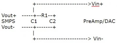
Thks for the lead, any diagram, actual values of component & connection how it is done?
So the switch frequency is 70kHz, we think. Do u know the Iq of the ckt it will supply?
The 70kHz means u wont be able to hear it, but 200mV ripple may perhaps create some unwanted effect...? Anyways u want less ripple.
The SMPS is likely switching with shorter than 50% duty cycle pulses and the rise/fall times of the switch current is likely short. Guessimate 10% of Tp (Tp is 14us (70kHz)) so 1.4us.
There is some Rout of the SMPS, and u probably have some wiring, so there is some more impedance. U want 10mV ripple? Lets pretend Iq is 50mA. C=I*dt/dv = 50m*1.4u/10m = 7uF.
Choose 10uF. Go crazy and add 10ohm resistor between two caps, CRC, and u should see even less ripple.
Electrolytic with close leads, say 5mm, will do (Big electros are too slow). Using ceramics u need to use >> 7uF b/c they drop in capacitance as voltage is applied.
Layout (where u place the caps) is important. Think smallest possible loop for supply and return of current in/out of cap.
Appreciate your coming in, on the actuals!
Is my understanding correct?
R1=10ohm (0.25W?), C1=C2=20uf cermaics/10u electrolytic.
Just curious, how is 70kHz determined? I happen to use Meanwell's LRS150
Would hope go below 1uV ripple
Does Iq relates to operating or quiescence current of PreAmp/DAC?
Is my understanding correct?
R1=10ohm (0.25W?), C1=C2=20uf cermaics/10u electrolytic.
Just curious, how is 70kHz determined? I happen to use Meanwell's LRS150
Would hope go below 1uV ripple
Does Iq relates to operating or quiescence current of PreAmp/DAC?
Attachments
Last edited:
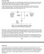
Adding to what I've already posted, and Tomchr's comments: you just don't have to reinvent the wheel here!
Look at detailed references like the excellent Analog Devices 'Op Amp Applications Handbook (Walt Jung, 2005): it's available free, online, as a PDF and will reward close & repeated reading at any level.
Anyway; here's one suggestion it contains, in a section you really ought to read: the voltage noted is not important - how the idea works, is - it will work exactly the same, at 30v in, or 300v come to that:
Attachments
Last edited:
Appreciate your coming in, on the actuals!
Is my understanding correct?
R1=10ohm (0.25W?), C1=C2=20uf cermaics/10u electrolytic.
Just curious, how is 70kHz determined? I happen to use Meanwell's LRS150
Would hope go below 1uV ripple
Does Iq relates to operating or quiescence current of PreAmp/DAC?
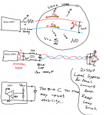
Tomchr mentioned 70kHz... I dunno, but it is high frequency ripple. Here's a suggestion. U dont want a very large C near the output b/c u dont know how the feedback loop inside the SMPS is... There should be a datasheet stating max C. If you buffer the output with some resistance or better a choke, even a CM choke, u can probably go much bigger with the C since u probably isolate the large C from the feedback loop inside the SMPS that way.
Ripple currents into the small cap can be high and with fast edges, so keep that first loop as small as possible.
How much C u need near your circuit being powered depends on it's output (load) currents and if they are pulsed as in a class-B type or if they are averaged to a constant value as in class-A. Treat the circuit being powered as if being fed with a high impedance power line, (current source), and the local caps should provide all currents for the signals. U can figure the slew rate if u know the load and signal amplitudes. Then figure out minimum C using C=Ic*dV/dt.
If u want to go advanced build cap-multipliers and cascade filters etc, but the impression is that u are not that experienced yet...?
Attachments
I've used the small, PCB mount Murata and Meanwell DC-DC converters -- in addition to the filtering on the output (or use of an LDO post regulator) you might find it helpful/necessary to put 100uH on the 5V input to the DC-DC converter. These devices radiate in both directions.
If Jan had some "Simple Switchers" available they'd be an excellent solution --
If Jan had some "Simple Switchers" available they'd be an excellent solution --
HeyMartin, I took a handle on Analog Devices 'Op Amp Applications Handbook (Walt Jung, 2005), I think is way-beyond my current apprehension level.Oops. The formula is C=i*dt/dv... sorry
Thks SemperFi, finally able to confirm meanwell LRS-150 SMPS freq is 65KHz instead of 70KHz.
Let me parrot what you mention:-
Tp would be 15.38uS, 10% becomes 1.54uS
Iq of the ckt is betw 14mA to 50mA (refers to quiescent current of whole Amp right?)
for 10mV ripple, Iq 50mA; C=I*dt/dv = 50m*1.54u/10m = 7.7uF => ok nearest 10uF (Ceramic cap 5mm close leads)
From here on i am lost, dint get how to sandwitch 2 caps with 10ohm.
I can partially understand smallest loop for supply with 1uf,
But how complete the CRC of 10ohm, 7uf ? you have a complete diagram with components values?
Supposely target is 50uV ripple, then C becomes 1540uF?
What happen if I use it to supply whole Class D Amp - max loading of 4.5A, can anything be done?
Sorry am a novice to electronics here.
HeyMartin, I took a handle on Analog Devices 'Op Amp Applications Handbook (Walt Jung, 2005), I think is way-beyond my current apprehension level.
Thks SemperFi, finally able to confirm meanwell LRS-150 SMPS freq is 65KHz instead of 70KHz.
Let me parrot what you mention:-
Tp would be 15.38uS, 10% becomes 1.54uS
Iq of the ckt is betw 14mA to 50mA (refers to quiescent current of whole Amp right?)
for 10mV ripple, Iq 50mA; C=I*dt/dv = 50m*1.54u/10m = 7.7uF => ok nearest 10uF (Ceramic cap 5mm close leads)
From here on i am lost, dint get how to sandwitch 2 caps with 10ohm.
I can partially understand smallest loop for supply with 1uf,
But how complete the CRC of 10ohm, 7uf ? you have a complete diagram with components values?
Supposely target is 50uV ripple, then C becomes 1540uF?
What happen if I use it to supply whole Class D Amp - max loading of 4.5A, can anything be done?
Sorry am a novice to electronics here.
Please note these are just suggestions. And the value we came up with was minimal for the target ripple.
We dont know the shape of the ripple or it's true value, since for that you must measure with an oscilloscope.
I'd just place a small ceramic and a bulk electrolytic close to the output of the power supply, then a series resistor of 10ohm, or an inductor, then new bulk electrolytic, and maybe a faster ceramic or film as well, but be carefull, it may resonate.
No need to go too theoretical, but here's an attempt:
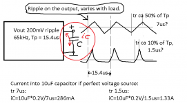
The shape of the ripple is unkown and can be anything from a 50% saw tooth to short but sharp spikes, the ripple is supposedly 200mV in value (peak? or is it average value?).
For the first cap on the output, the ripple will cause large currents, and you want to keep those currents close to the power supply. Then you can have some resistance, or inductance, which will limit the current spikes from going down the wire (antenna). 50mA iq means even a 10ohm in series will only drop 500mV DC.
You have two things to think about (and a bazillion more since this is HiFi). First the power supply and the loading of it, then the circuit and it's loading of the power rail. Usually small signal circuitry like this runs in class-A or close to it and the average current draw is steady, DC-ish. But you still want local decoupling so current peaks are not drawn through long wires and from bulk caps far away. The minimum size of the local cap is determined by the peak current (iC) and it's rise time (dt), oh and the max ripple you want to allow (dv). Cmin=iC*dt/dv
How figure dt and dv? Well slew rate is 2Pi*f*V which is the same as dv/dt. So say 10kHz at 2Vpp the SR is 2*Pi*10000*2=0.126V/us. Or 1V per 7.96us. So what's the current drawn from the power rail? Well say 2kohm load, this requires 1mA to swing 2V. Say you want max ripple, or voltage droop from this load current to be 1mV. The C required is C=1mA*7.96us/1mV = 7.96uF minimum.
As mentioned you have too many variables that you are uncertain about, so just use a common value for the bulk caps, say 47uF to 1000uF, or more, use a standard solution... experiment.
Sorry no precise answer, but too many variables and layout place a role too, so just go safe and use standard filter, say 1000uF - 10ohm (or an inductor) - new 1000uF, or something like that.
Attached drawing of ripple current into a 10uF cap if power supply is a perfect voltage source (that it delivers the current). Notice how the different ripple wave forms alters the current into the same cap.
Attachments
Last edited:
add an air cored inductor after the cap and then a further cap to change the rC filter to an rC{R+L}C filter.
the Pi filter has two stages and works better at attenuating the interference.
The inductor does a good job of attenuating the HF spikes, again better than putting in an extra RC
the Pi filter has two stages and works better at attenuating the interference.
The inductor does a good job of attenuating the HF spikes, again better than putting in an extra RC
I threw this app note up earlier, should be useful. Designing Second Stage Output Filters for Switching Power Supplies | Analog Devices
(^ CLC filter)
Overprovisioning the current capability on the inductor isn't hard when you're talking a preamp, so use a cored inductor instead of air. Can easily get a filter with very modest capacitance with an f3 below 1 kHz, which means you're down about 60-70 dB by 60 kHz? CRC is probably more than enough.
But I'd be throwing a scope on the output of the preamp to see what's actually making it through in terms of intermodulation products in the audio band.
Last edited:
Thanks for link, as usual AD app notes are good reads.I threw this app note up earlier, should be useful. Designing Second Stage Output Filters for Switching Power Supplies | Analog Devices
(^ CLC filter)
Overprovisioning the current capability on the inductor isn't hard when you're talking a preamp, so use a cored inductor instead of air. Can easily get a filter with very modest capacitance with an f3 below 1 kHz, which means you're down about 60-70 dB by 60 kHz? CRC is probably more than enough.
But I'd be throwing a scope on the output of the preamp to see what's actually making it through in terms of intermodulation products in the audio band.
Yeah I agree a scope is required to check the results of filtering, as well as other stuff.
Like to thk all of you for sincerely trying to guide and share years of experience.
I think i will take awhile to digest :-
for KISS, wld appreciate some suggest on values on how to filter -
Meanwell LRS-150 SMPS freq: 65KHz
Ripple =200mVpp
Output = 4.7A (i am using it on a integrated amp - let suppose max current drawn cld remotely be 4.7A)
if Ripple can down by 60-70dB, wld be good!
With a few mA or tens of mA perhaps...A few amps, no way. Well, unless you go huge on the filter of course, but 60dB? ferget it.
I'd be very happy if only 200mV ripple on a device drawing 4.7A.
65kHz, cant be heard anyways.
Reduce ripple to light circuitry, (preamp etc), not the PA.
I'd be very happy if only 200mV ripple on a device drawing 4.7A.
65kHz, cant be heard anyways.
Reduce ripple to light circuitry, (preamp etc), not the PA.
- Status
- This old topic is closed. If you want to reopen this topic, contact a moderator using the "Report Post" button.
- Home
- Amplifiers
- Power Supplies
- Reduce SMPS ripple noise for PreAmp?