What chances are there that the cheap, easy, Zener, resistor, and capacitor used to make secondary voltages, say for a pre-amp or equalizer, being noisy as they are, would add overhead to the opamp's ability to reject noises and other undesired effects on it's ability to operate in micro-distortion performance. (what a sentence !)
The answer lies in computation, calculations and more computation: how much ripple is present in the first place, how much does the simple reg eliminates, and what is the opamp's PSRR.
If the result ends up being drowned in the native noise, then it's OK.
In the seventies, when the range of monolithic regulators was much more limited, this solution was very often used, when one would need, say +31V or any other non-standard voltage, and it posed no particular problem.
A typical open-loop, optimal simple reg + gyrator combo will typically provide 60 ~ 70dB rejection (limited by the Early effect).
If the opamp adds another 80dB, it's probably going to be sufficient, but you need to do the maths for each specific case.
Regarding "micro distortions", dunno....
I worded that in a complex way. What I meant was can all the different types errors add together and make the opamp "too busy" to compensate for them all ?
I suppose those active constant current supplies that feed each section of a complex opamp might individually manage each type of distortion at the points they normally enter the signal. I was so happy to see such a simple zener regulator working well to feed a TL071 in a bass guitar amp, I'd toss that out to cyberworld and see what came back.
They may not do so well in hifi. Some music instrument amps are not hifi, they have intentional distortions to give a sonic personality to the instrument.
I don't think simple resistive long tails would do nearly as well.
Last edited:
I think you are over-thinking this.
We have caps. Supply "noise" (unspecified!) can be reduced with caps.
Nearly all small-signal audio can be done with basic passive power supply and a few stages of R-C filtering.
Especially with opamp chips which are half regulators inside. (Nearly every gain stage works against a CCS.)
Regulators have a point when you must go right to the rating limit of your amplifier to make your desired signal voltage. Pro audio regulates to +/-15V or +/-18V so that it can meet the historical level of 6V6 line amps. Hi-Fi and instrument can be run 10dB lower and can use sloppy 20V-30V power without fear of overvoltage. (All the lamps in your house will explode before your TL072 does.)
Regulators "have a point" when the amplifier designer can't handle uncertain supply voltage. There are several classic designs which work OK at, say, 9V, but collapse at 6V and do not make use of higher supplies effectively. A ton of phono preamps were this way and for common wall-voltage variation and multi-stage R-C filtering they gave no trouble.
As Elvee says: C, C, and C!! Don't dizzy-tither, put numbers on it.
Well I can't hear anything wrong with line level signals powered by noisy 15v zener/resistor regulators. Again I just didn't know if it helps to reduce the everything thrown at it situation. They only say how it performs with reference to one adverse condition at a time, not all of them at once.
Why use zeners when you can use this, for $7?
LM317 LM337 AC-DC Adjustable Dual Voltage Regulator Regulated Power Supply Board | eBay
LM317 LM337 AC-DC Adjustable Dual Voltage Regulator Regulated Power Supply Board | eBay
Oh good! Then you make a BUNCH of noise!!I got a big bunch of zeners on Ebay for a few dollars, I think 5ea 14 values for about $4. Unlike lateral mosfets from Ebay, these work ok.
Seems I remember seeing 1/4 volt or more noise, I will measure again. I was thinking it works the CC sources harder than intended. That would be 0.016% noise that works it.
I'll have to try a gp transistor with capacitor feedback.
Sometimes I'm too impatient or the shipping cost is more than the part. And then... is the wait.
I'll have to try a gp transistor with capacitor feedback.
Sometimes I'm too impatient or the shipping cost is more than the part. And then... is the wait.
Last edited:
A Linear Technology LT317 3-pin regulator specs at 0.001% noise; about 150u Volts on a 15-volt supply. That, in combination with >80 db of ripple rejection, makes it pretty hard to beat for $2.15 (from Arrow Electronics, free shipping).Seems I remember seeing 1/4 volt or more noise, I will measure again. I was thinking it works the CC sources harder than intended. That would be 0.016% noise that works it.
Zeners regulators can work well when supplied by a constant current source. A simple shunt using resistors and bypass caps work OK if the current is small and the raw voltage is large and clean(ish). Or the large R value approximates a current source compared to the parallel zener and bypass caps impedances. I wouldn't hesitate to use them to supply an DIY op-amp or 2 with cherry picked parts and large headroom. Otherwise 3T V regs rule for lower headroom apps.
for a zener shunt regulator the ripple attenuation is a simple voltage divider 20*LOG Rl/(Rin+Rl) in dB
Rin is the input series impedance
Rl = Rz//Xc// Rload , where Rz = dynamic zener impedance , Xc = bypass cap " , Rload = Vz / (Iload)
in the case of a real constant current source using a PNP transistor, looking into the collector, Rin ~ 1/hoe or roughly 50K ohms or more.
for a simple series resistor, Rin is ~ (Vi-Vz)/ (Iz+ Iload) note a large Rin value is better attenuation, so smaller currents and larger headroom voltages are best.
Last edited:
I run into so many different voltage needs, I would need to keep at least 10 each +/- adjustable regulators or for most situations do the 78Lxx and 79Lxx stretch. They can easily be adjusted to voltages higher than the base voltage such as 78L12 can use a resister divider to make it into a 15 volt regulator.
I suppose I could grab a few next order I make from the real companies that sell only 1st tier quality. I was just thinking today to replace the FET's in a $20 IRS2092 500 watt Ebay amp. Get it all in one order. I do not like that what the heck is under the plastic feeling I get from those Ebay transistors and yes zeners too. They may be noisy rejects that should have been trashed.
Too afraid to use it on an Ampeg speaker cabinet. Got cold feet when I started looking at the speaker it would have run. The amp was damaged in shipping, the heatsink was cocked and a few components cracked loose from the board. Soldered it back up and it seems to be ok, but the fear factor has been keeping it shelved for desperate times. They said a new one was mailed out Nov 13, but no sign of it as of Jan 10. Another reason I'm fed up with that source.
Last edited:
... in the case of a real constant current source using a PNP transistor {with no emitter degeneration or feedback}, looking into the collector, Rin ~ 1/hoe or roughly 50K ohms or more ...
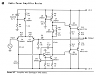
A 2-transistor feedback current source, or a 1-transistor current source using an 8.2V zener diode and emitter degeneration resistor, can each give a current source whose output impedance is 1E6 ohms. Examples of these two current source circuits appear on page 60 of Bob Cordell's power amp book: Q6-Q7 , and Q3.
_
Attachments
Last edited:
So far a simple 4.7k resistor and 1W 15v zener shunt, feeds a TL071 and low voltage input section.
I got a laugh, expecting hifi perfectionists to sneer that off, I did. I suppose the opamps can compensate all stated adverse conditions in one installation. I'll have to wire one up and toss in .5v power supply noise on both rails, some large input common mode noise or ripple, capacitor and inductive load, running a gain of 1000 as near as it can to the GBW, hang a hot resistor over it to heat it near max, no decoupling caps, and whatever I can cook up, then see how it does.
Or find if it is mainly able to manage one far side adversity.
- Status
- This old topic is closed. If you want to reopen this topic, contact a moderator using the "Report Post" button.
- Home
- Amplifiers
- Power Supplies
- Simple Zener Secondary Voltage Regulators