Gotcha, yes, it would be a good idea to twist the supply wiresA metal case does not protect from getting radio interference over the antenna.. er, power wires into it.
In general I find it rather disturbing, if not dangerous, if a mains power standard plug (powercon) is used for a much different purpose and a possible confusion of the wires. I mean, if the powercon is plugged in - as it's intended -
with mains power voltage it could start a fire, the capacitors can explode. That's a kinda high risk, I would at least put fuses in it and after the fuse diodes to ground, that way it could still be damaged but the fuses will blow because of the high current through the diodes while the negative halfwave. And no, "it's just me who plugs it in" isn't an excuse.
Edit: I would also use different types of plugs for both voltages, an accidentally switch won't make anyone happy either.
That's true. I have a similar set up, I'm using speakon for the power, if I used them for speaker anywhere in my system I would change them. Trusting oneself to always be paying proper attention and getting it right is a mistake. I would advise the OP if he uses the dual voltage system to make it impossible to connect them incorrectly
IEC power connectors are only to be used on mains power nothing else.....
for connecting the dc supply lines other types of power connectors are to be used,
usually the round screw type male and female types....
the supplying end can be female plug types while the receiving end can be male types...
use of diodes of appropriate voltage and current in series with the dc lines can be used to prevent possible arcing on disconnecting the male and female plugs...
Hi scottjoplin,Probably not, you'd have to check that the output stage could run at the higher voltage. You could safely use the lower tapping for both the VAS and output stage, but this would restrict the maximum output. It may also be that the higher voltage winding cannot supply the necessary current for the output stage
That does work, at those voltages there's probably even quite little to be gained from running dual voltages (at least that's what my little spreadsheet tells me).
@ all: I have had the system up and running in a very improvised way: the amp section in an old enclosure, and the PSU section with all the caps on a piece of wood and the two connected with mains triplet cable and the Powercons.
The "signal star ground" in the amp enclosure wasn't connected to the enclosure, and there was no safety ground (naughty, I know).
The amp works fine, with no humming and no interference that I noticed.
Just to be clear, I want to do more or less what I just described, but using metal enclosures for both amp and PSU sections and having the whole thing safely grounded!
Cheers
Es
have a read of this old Thread.
It has a lot of Safety related content.
understanding star grounding
It has a lot of Safety related content.
understanding star grounding
There are good reasons for putting the voltage reference point near the circuits which use it. How this is then connected to safety ground is a separate issue.scottjoplin said:The star I was referring to was the one he shows in the amp enclosure, there is no need for it to be there.
So the star is not the signal reference point? Then it isn't a 'star ground' but merely a junction of a few wires. There is certainly no reason to join the two PSUs in the amp chassis. Doing this creates a loop, because the two PSUs cannot be separate anyway as they share a secondary CT.
There are good reasons for putting the voltage reference point near the circuits which use it. How this is then connected to safety ground is a separate issue.
The star ground got nothing to do with the safety ground, the star ground is for optimizing signal cleanliness, especally eliminating or at least minimizing ground loops. Voltage reference points close to the circuits can be important, noise elimination is much more important in an amplifier.
Hi Guys!
Better give you an update on the amp: it's finished, doesn't hum and performs as it should (I'd say it sounds excellent, but don't want to start a debate on whether or not an amp should "sound" like anything).
I followed the advice on hooking up the caps correctly, and have twisted the wires wherever possible. There's a central "function" ground (0V) in the amp enclosure (towards the front plate in the middle), which in turn is connected to first the amp enclosure and then the PSU enclosure where it also runs to ground.
I decided not to run the secondary voltage for the inputs, but it doesn't seem to be lacking anything!
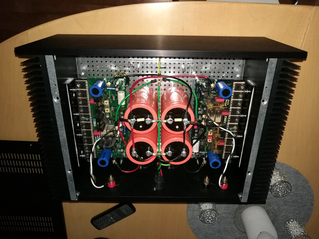
It's now got 60.000uF (the silver caps) per rail in the PSU enclosure and another 13.600uF (the orange caps) per rail in the amp enclosure.
The two enclosures are connected with a shielded cable carrying -DC, OV and +DC plus an additional cable for safety earth.
DC is switchable (actually on the primary side) between +-72V and +-88V, but I've only been listening with the +-88V so far.
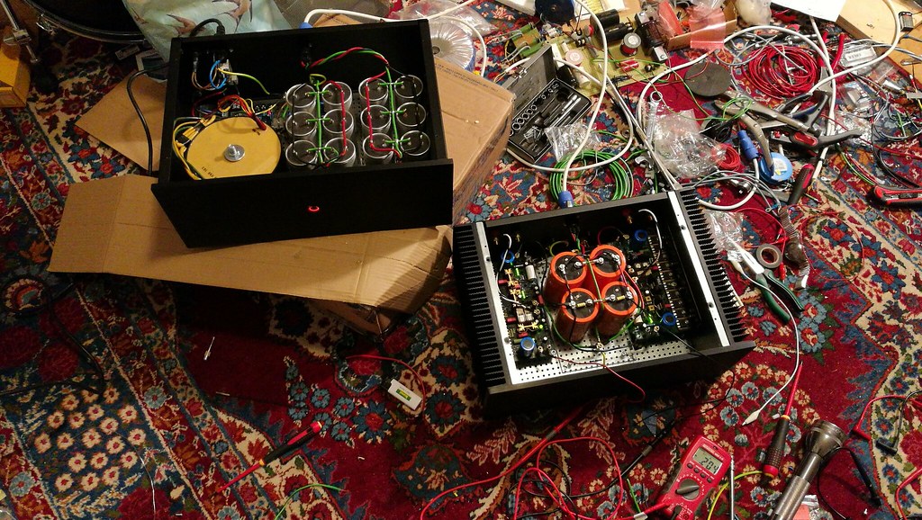
Excuse the mess!
And this is how the whole setup now looks:
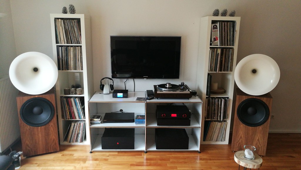
Next project will be some Pass First Watts for the horns
Cheers

Better give you an update on the amp: it's finished, doesn't hum and performs as it should (I'd say it sounds excellent, but don't want to start a debate on whether or not an amp should "sound" like anything).
I followed the advice on hooking up the caps correctly, and have twisted the wires wherever possible. There's a central "function" ground (0V) in the amp enclosure (towards the front plate in the middle), which in turn is connected to first the amp enclosure and then the PSU enclosure where it also runs to ground.
I decided not to run the secondary voltage for the inputs, but it doesn't seem to be lacking anything!
It's now got 60.000uF (the silver caps) per rail in the PSU enclosure and another 13.600uF (the orange caps) per rail in the amp enclosure.
The two enclosures are connected with a shielded cable carrying -DC, OV and +DC plus an additional cable for safety earth.
DC is switchable (actually on the primary side) between +-72V and +-88V, but I've only been listening with the +-88V so far.
Excuse the mess!
And this is how the whole setup now looks:
Next project will be some Pass First Watts for the horns
Cheers
I plan to test a power supply (probably regulated) in a separate enclosure from the one of the amplifier. There will be a safety earth connection for the power supply chassis but the power supply 0V will not be connected to it.The Protective Earth wire gets connected to the mains Chassis/Enclosure. That is a SAFETY connection and has absolutely nothing to do with obtaining a good working audio system.
There is a second rule: All exposed conductive parts should be connected to the Protected Chassis/Enclosure. Again this has nothing to do with obtaining good quality audio. It is purely SAFETY.
However, both the PE connection and the extra "All exposed parts" connection can give an additional route for interference reaching the audio circuitry.
Scott has mentioned
The power supply will be floating down to the inside of the amp enclosure. I wonder about screening the cable between the enclosures, the screen being connected to the power supply chassis with a cap.
It should be so the fuse blows if mains voltage gets into the circuitThere will be a safety earth connection for the power supply chassis but the power supply 0V will not be connected to it.
A fuse blows for an excess of current. The protection of persons is achevied using a circuit breaker based on the difference between the currents in the live and neutral wires of the mains (for more than 30 mA in France).It should be so the fuse blows if mains voltage gets into the circuit
Lab power supplies have their output usually not connected to the chassis and earth and people using them are more exposed than users of standard audio devices.
As to the mutual grounding of two seperate chassis, what I did was to simply connect the two together via a heavy lead. That way they are mutually grounded.
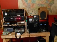
On the shelf to the left is the amplifier, on the right is the 4kv power supply. Both are kinda big, but the supply is also pretty darn heavy. The power supply is controlled remotely from the switches on the amp, and the mains feed also comes from the amp to the HV supply. They are electrically bonded with a 10 gauge cable between both chassis.
While this may not be an audio amp, it uses electrons just the same.
Attachments
As you say, the chassis of a lab power supply is connected to earth for safety reasons (only). The outputs are isolated and supply current to devices which schield of do not need to be connected to earth for best EMI rejection, even more, should be avoided in absence of hazards, according to EMC specialists.Lab power supplies are not double insulated, i.e. not ClassII. They are connected to PE making them ClassI
The outputs are isolated.And usually with a connection to PE protected chassis if required.
- Status
- This old topic is closed. If you want to reopen this topic, contact a moderator using the "Report Post" button.
- Home
- Amplifiers
- Power Supplies
- Grounding with separate enclosures?