your layout will not perform at the best that a 317 can achieve.
How can you measure the difference? a pulse on a heavy load?
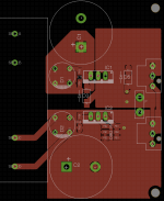
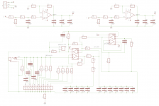
I'm getting some other PCBs made up soon so I thought I'd get some new PS ones done at the same time. I've updated the design to address several of the comments so far and decided on a fixed +-15V output.
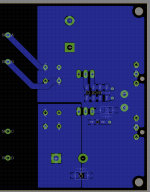
As usual the graphics output from Eagle are a bit crappy, in places it looks like one side of the SMD pad is not fully isolated. I've checked that they are and run a DRC to be sure.
... Does this look like an improvement?
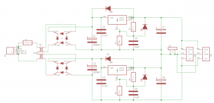
As usual the graphics output from Eagle are a bit crappy, in places it looks like one side of the SMD pad is not fully isolated. I've checked that they are and run a DRC to be sure.
... Does this look like an improvement?
Attachments
Use run-of-the-mill electrolytic capacitors for C4 and C7. Some brands of LM317 become unstable when the losses of the output capacitor are too small. I once connected an LM317 to two 10 uF X5R ceramic capacitors in parallel, which turned my LM317 into a sawtooth oscillator. The capacitors themselves worked as loudspeakers, so you could hear a beeping sound coming from the board. Connecting a 47 uF cheap aluminium electrolytic capacitor in parallel solved the problem.
This!
Using 3-pin regulators off-piste: part 3
HTH.
According to the TI datasheet for the LM317 an output capacitor is not needed for stabilityI think most of these regs need a lossy cap at the output for stability. Usually the data sheet gives the minimum ESR required in the output cap.
Jan
I usually avoid tantalum capacitors because tantalum is a conflict mineral and parts manufacturers never specify where they get their tantalum from, but yes, I think they should do fine.
The application note Martin referred to shows a resonance frequency of 22 kHz at 820 nF load for a 10 V regulator without adjustment pin decoupling. That boils down to a regulator output inductance of 1/(4 pi^2 (22 kHz)^2 * 820 nF) ~= 63.824 uH. With adjustment pin decoupling, the high-frequency loop gain increases, which makes the inductance decrease: 63.824 uH * 1.25 V/10 V ~= 7.9779 uH. With a 1 uF output decoupling, the resonant frequency will be about 56 347 Hz and the reactance at resonance will be about 2.8245 ohm. With 6.6 ohm ESR, your capacitor then has a Q factor of only 0.42796, which is absolutely perfect for this application.
The only thing you have to be careful with is decoupling capacitance in the equipment you want to supply with this power supply. If it has high-Q decoupling capacitors with a total capacitance >> 1 uF, you could still get problems.
According to the TI datasheet for the LM317 an output capacitor is not needed for stability
Which doesn't help much, because in most practical applications there will be some local decoupling capacitors connected to the output anyway.
I also failed to find anything about the required ESR in any of the LM317 datasheets I've seen. There are sometimes plots of the regulator output impedance (on a very course scale with no phase plot) that you can use to estimate the resonant frequency, but that's about it.
That's a good reason to avoid them... I'll see if I can find something similar that will work. And thanks for doing the maths, I'm still fairly new to this and it takes a bit of time for me to absorb the information.I usually avoid tantalum capacitors because tantalum is a conflict mineral and parts manufacturers never specify where they get their tantalum from
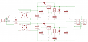
I've attached a schematic of the phono stage I plan to use this PS for... I think I should be okay as the most of the decoupling happens on the output side of the DC input op amps.The only thing you have to be careful with is decoupling capacitance in the equipment you want to supply with this power supply. If it has high-Q decoupling capacitors with a total capacitance >> 1 uF, you could still get problems.
Attachments
I don't see any local supply decoupling at all for the DC op-amps.
I can't believe I missed that! Thanks... would 100nF X7R caps be a sensible starting point to decouple those amps without causing problems with the PS regulators?
In my research, I found that there is a pretty big difference between BRANDS of LM317 type three-terminal regulators. For example, in the datasheet specifications, the Linear Technology LT317 has 16 db better ripple rejection and 10 db less noise than the T.I. part. The LT317, of course is ~ $2 each compared to the 50¢ T.I. LM317; but for most projects only requiring a few, it's money well spent, IMNHO.
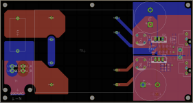
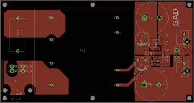
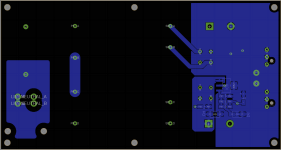
I'm a bit stumped... I've got some new boards made up (schematics & layout below) and I'm getting +-28V at the output with 1k & 12k resistors I was expecting 16.25V. I've double checked the orientation of all the polar components, the only thing I can think is that I damaged the regulators somehow - or I've made some other dumb mistake with the circuit, but I've been through it a few times now and can't see what the problem is.
Attachments
Some version of the lm317 work with only 5mA of output current.Minimum load current? If I remember it correctly, an LM317 requires 10 mA of load current to maintain regulation.
That allows R3 to be 240r. If 10mA is needed then R3 becomes 120r
Last edited:
Thanks, I think I understand now... the minimum load current is achieved through R3 + R1, so if I make those 120R and 1400R respectively the output should be 15.8V with creating a load current of 10.4mA.
I guess to correct the mistake on the board I've already constructed I can just add 1k8 resistors from the +&- outputs to ground in parallel with the 13k already provided by R3 & R1.
I guess to correct the mistake on the board I've already constructed I can just add 1k8 resistors from the +&- outputs to ground in parallel with the 13k already provided by R3 & R1.
- Status
- This old topic is closed. If you want to reopen this topic, contact a moderator using the "Report Post" button.
- Home
- Amplifiers
- Power Supplies
- Is there anything wrong with this PS design?