http://www.tedpavlic.com/teaching/osu/ece327/lab3_vreg/lab3_vreg_lm317_example.pdf
I imagine a NE5532 driving two higher gain power transistors and LED voltage reference could be a better LM317. Make it a simple as possible. Above some working of the 317.
I imagine a NE5532 driving two higher gain power transistors and LED voltage reference could be a better LM317. Make it a simple as possible. Above some working of the 317.
That's a "Sulzer Regulator", described in The Audio Amateur in the early 1980's, and "improved" a few years later -- works pretty good. Uses a NE5534 error amp. Lots of tantalums. I don't think LEDs were used for anything but illumination at the time (and only readily available in one color.)
Sure he means rail to rail.Do you mean rail-to-rail??? The OPA2227/2228 are NOT that, and are much slower than a NE5534.
The circuit does not need rail to rail op amps.
They are powered with +15V -15V.
Once steadied, inputs are at 0V, outputs are at 0V.
Inputs and output cannot be more far from rails.
The problem I see is that in the ideal world the supply would need a little RC filtering to the op amp. Seeing as the real LM317 has none maybe I should trust the NE5532 to do what supposed LM741 inside the LM317 does. I can RC filter the LED supply as even at 5 V it should be OK to drop 3V. A rail to rail op amp would help. I guess we accept some compromise there. A DIL 8 holder so as to try that later. I have some JFET CCS. I doubt they will be the right thing.
ATC Semitec E-202~E-562 Current Limiting Diode CRD - 2.0mA | Rapid Online
One thing I did try was a voltage doubler to the LED and op amp ( years ago ). If a capacitor input type it can use the same AC supply. After filtering it may not give vastly more driving volts. However enough to overcome the op amp running out of headroom. If very careful the doubler is better from point of view of any noise even. If using 15 V for a 12V PSU one starts with 30V.
I plan to use an over current bolt on. The 0R22 transistor summing resistors would give too small a potential difference to be useful. They would work fine with TL081 as comparator. It's internal resistor allows it to short the LED. Although crude it should be usable. I suspect hysterisis not useful when this type of use ( 10K 10 M for example, no harm trying ). Sometimes a simple resistor is all the current limiter you need. If so it can be part of a RC filter. Junk the TL081 if so. I've never used a JFET comparator, I'm told it's OK. If not a 741 generic. Often better than real comparators if sourcing and sinking. Could be a noise source.
At the end of the day ideas like this are useless if they don't do something better. To me the LM317 is near perfect for any real application. Noise can be bettered and if looked at as a non comersial product can be kept simple. The TL431 is so close to being a good idea. It is a zener type device with gain options and an op amp internally. The salvation of 431 is the data given. When used with a big darlington the simplicity is excellent.
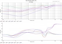
Here is my test data when trying to see what very simple arrangements would do. All are if you like the most simple data sheet ideas. Allowing that as TL431 is a choice I felt it's slight extra complexity was OK although unfair to the others if counting parts used. For example I got the LM7812 to -104dB ( ref 1 V ) recently and LM317 to the -111db baseline which alas is as far as I can go. Note I give a shorted reading this time. On relflection the simple amplified zener is not too bad as a starting point. Sorry I didn't keep the circuits. If I remember correctly 0.5A load at 12 V.

ATC Semitec E-202~E-562 Current Limiting Diode CRD - 2.0mA | Rapid Online
One thing I did try was a voltage doubler to the LED and op amp ( years ago ). If a capacitor input type it can use the same AC supply. After filtering it may not give vastly more driving volts. However enough to overcome the op amp running out of headroom. If very careful the doubler is better from point of view of any noise even. If using 15 V for a 12V PSU one starts with 30V.
I plan to use an over current bolt on. The 0R22 transistor summing resistors would give too small a potential difference to be useful. They would work fine with TL081 as comparator. It's internal resistor allows it to short the LED. Although crude it should be usable. I suspect hysterisis not useful when this type of use ( 10K 10 M for example, no harm trying ). Sometimes a simple resistor is all the current limiter you need. If so it can be part of a RC filter. Junk the TL081 if so. I've never used a JFET comparator, I'm told it's OK. If not a 741 generic. Often better than real comparators if sourcing and sinking. Could be a noise source.
At the end of the day ideas like this are useless if they don't do something better. To me the LM317 is near perfect for any real application. Noise can be bettered and if looked at as a non comersial product can be kept simple. The TL431 is so close to being a good idea. It is a zener type device with gain options and an op amp internally. The salvation of 431 is the data given. When used with a big darlington the simplicity is excellent.
Here is my test data when trying to see what very simple arrangements would do. All are if you like the most simple data sheet ideas. Allowing that as TL431 is a choice I felt it's slight extra complexity was OK although unfair to the others if counting parts used. For example I got the LM7812 to -104dB ( ref 1 V ) recently and LM317 to the -111db baseline which alas is as far as I can go. Note I give a shorted reading this time. On relflection the simple amplified zener is not too bad as a starting point. Sorry I didn't keep the circuits. If I remember correctly 0.5A load at 12 V.
RHP zero?
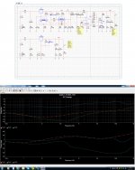
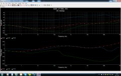
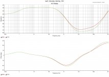
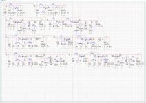
I simulated rough, simplified circuit of LM317 and plot the loopgain.LM317 have large voltage gain with one stage amplifier but the gm is strongly degenerated by R2 12kohm (and reverse polarity current from Q2345 via current miller). So its open loop gain crossover point is roughly calculated 1/2/pi/12kohm/(30pF+30pF)=220kHz.After that frequency C2 (and C1 if without C3) create RHP zero, right? I am a amateur, so please criticize if I am wrong.
78XXs are non degenerated gm stage with C-B millar compensation ,therefore less risk of RHP zero I think. 78XXs look more suitable for hybrid opamp + 3 teminal regulator circuit from this perspective. Also feed a signal to the 78XXs GND terminal ,where is the noninverting input of compensation stage. So it will get a zero but this time LHP, it is good thing.
Attachments
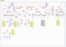
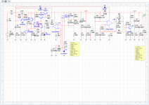
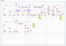
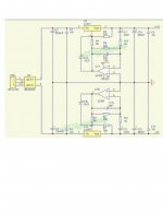
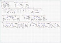
There are circuits of LT1083 (LM317) .
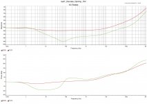
There are simulations of LT1083 (LM317) .
Chose any circuit you want.
.
Specially disigned for low noise applications such as mic amp, RIAA amp, DAC amp, play back amp and so on.
.
There are simulations of LT1083 (LM317) .
Chose any circuit you want.
.
Specially disigned for low noise applications such as mic amp, RIAA amp, DAC amp, play back amp and so on.
.
Attachments
Last edited:
There are circuits of LT1083 (LM317) .
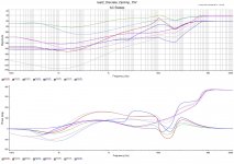
There are simulations of LT1083 (LM317) .
Choice any circuit you want.
.
Specially disigned for low noise applications such as mic amp, RIAA amp, DAC amp, play back amp and so on.
All circuits are "+15V" designed.
.
One of the circuit was changed and simulation was changed.
.
Administrator, please DELETE post #335 .
.
Attachments
Last edited:
That schematic is totally unreadable. And, what does it have to do with the topic of LM317 load capacitance?
Nothing.
It is just some cascades of common circuits, bolted together without sense
with the intention to impress with large numbers.
BTW, 245 dB is about the path loss of a VHF signal between an
antenna directed to the moon, traveling 380,000 Km, being bounced
back from the dusty moon surface and traveling back another 380,000 Km
to the same antenna.
It takes abt. 1 KW of RF power and 24 dB antenna gain, and an
excellent preamplifier, but you then can hear the echoes just so
in the noise after 2.5 seconds of flight time at light speed.
BTDT, was fun.
Last edited:
Yeah !BTW, 245 dB is about the path loss of a VHF signal between an
antenna directed to the moon, traveling 380,000 Km, being bounced
back from the dusty moon surface and traveling back another 380,000 Km
to the same antenna.
It takes abt. 1 KW of RF power and 24 dB antenna gain, and an
excellent preamplifier, but you then can hear the echoes just so
in the noise after 2.5 seconds of flight time at light speed.
I love this.
What about the pictures transmitted from Pluto ?
Phone home.
You have a message from Andromeda.
In No 330 I gave graphs of the simplest TL431 using MJ3001 TO3 NPN darlington from my junk box. In fig 25 from the PDF it shows you how it only needs the minimum of extra parts over an LM317. Look also at the stability graphs. Very useful to have it clearly stated. I seem to remember a 22uF electrolytic will do the job ( some add a resistor ). Equally a 10 nF film or ceramic. Anything between may not work. TIP142 should cost less.
The beauty of the MJ3001 or whatever is a fuse might be all it needs as protection if the circuit is a known load and hardwired. I seem to remember the the ON version has lower noise.
NCP431: Voltage Reference, Low Cathode Current, Programmable, Shunt Regulator
http://uk.farnell.com/multicomp/tip142/darlington-transistor-to-247/dp/9294287
http://uk.farnell.com/on-semiconductor/ncp431aclprag/voltage-ref-shunt-2-5v-36v-to/dp/2318604
Very interesting final circuit here. BC337-40 might give the same with a chance to have more current. BC337 is almost as good as BC550C when noise. ( 0.6 nV/root Hz ). The gain of the 40 version is excellent. BC327 also when PNP. BC817W seems to offer lower power in SMD. That is a surprise as often SMD is better.
Simple Voltage Regulators Part 1: Noise - [English]
https://www.onsemi.com/pub/Collateral/BC337-D.PDF
- Home
- Amplifiers
- Power Supplies
- LM317 load capacitance