Better stay away from Kentucky Fried Chicken, too.Stay away from KFC a while long and get a DSO203?

At last I have found some simple LM317 data. This was before I sorted out the ground. First is a simple 7812 as in the data sheet. Next LM317. Note a small improvement in hiss and 317 deals with ripple better due to bad layout. Next where the thread started. 0R33+ 10 000uF post LM317 RC filter. I think that is not bad. The reference level is 1V and the actual output 12VDC. I forget what some of the data refered to. The hum was brought down to 3 dB above hiss levels at 1.5 amps. Adding a power transistor added very little hiss. The LD1084 was best of type. I did use TL431 as a reference device, I think On make has lower noise. If you prefer the added transistor try to run the LM317 at a higher supply voltage rather than use a PNP pass device. Stability is better. I used a voltage doubler to the input pin. In these graphs everything is near standard.
The above 0R33+ 10 000 uF was in reaction to this Wenzel circuit which wouldn't work so well for me, doubtless my haste to try it. I was asking a very simple question. Would not it do similar things. It became 0R1 and 10 000uF in the final version. I was inspired by Zobel circuits and asked could > 100 nF work. I think the simplicity of the pass transistor feedback loop helps it work when LM317/LD1084.
Finesse Voltage Regulator Noise! |
Finesse Voltage Regulator Noise! |
Reading the Wenzel notes again I have to specualte my idea could be as good or better. The only way with this set up would have been to build a gain of 20 amplifier to go before the analyser. OK, it would have been a poor attempt. All the same I would exspect the difference between standard LM317 and LM317+0R33+10 000uF to be greater than the near 4 dB seen as it is at the limit of that analyser. It might have been enough to see greater dB's. If I switch on my Eithernet via mains the whole graph shifts up and bounces. Realistically that's where the limit is in most modern houses. I built a lash up isolation transformer and solved that. It was a floating type made from two back to back types where number one was 12V and number two 9V at circa 160VA. 253V rms off load which is just OK. The proof was data could not pass. Hence all my dislike of earthing although one must. I also used if to remove a ground loop from my Panasonic TV + PVR.
So far I have learned much about the LM317. Thank you, audio diyers! I have gathered that a large capacitor on the output of a LM317 may not help much at all; in fact, it may make things worse (especially if it is a low-ESR "audio quality" cap) by creating resonance at higher frequencies. Some have suggested that indeed, a low-value resistor in series with the cap will tame this. It also appears that a large(r) value on the adjustment leg (220uF) lowers the noise significantly. This, in combination with a LARGE cap (10000uF) on the LM317 will bring the 120 Hz ripple rejection down to below 0.1 mV with 1 amp of current draw. There appears on the datasheet, however, one instance where a large cap on the output may well improve things---they show that, with 500 mA and 15 volts of Vin to Vout, that the 120 Hz ripple rejection goes all to hell when the output voltage ventures beyond 25 volts---getting 24db worse by the time the output approaches 30 volts!! This may, indeed, call for a MUCH higher value cap on the output;perhaps with that series small resistor. I am left wondering if this is also the case when the Vin-Vout is a more reasonable 5 to 7 volts. Has anyone ventured to measure that?
I think if you look at my graphs in 183 that isn't true. The system is stable and very low noise. I was very surprised also. If you look inside the working of the LM317 it looks to be like a very simple amplifier that might tollerate difficult loads. And so it does. It might be that near zero ohms and 1uF is more of a problem than 0R33 and 10 000uF. Whilst I have always made 1uF direct to the LM317 work I think I have seen the peaking you refer to. TNT Audio said similar things. Perhaps the question is what is the ideal capitance resistance filter that maintains stability. Ground connection etc are important, dead bug construction often better.
One reason we might be in trouble here is Douglas Self wrote that by simple maths the typical LM series regulator was infinitely better than lets say 10 000 uF. I have to say he is mostly right. Where I have doubts is that the typical final 1uF many use seems to be doing a lot of work. The regulator is busy bouncing both at input and output with it's 1970's op amp controling it. My use makes the LM317 work less hard and says a 10 000 uF is not bad at all as a reservoir. If the regulator works less hard I suspect the supposed advantage of shunt regulators is questionable. None of the regulators work very well at the beginings of RF. It is always the final shunt capitor doing the work. So the big following for shunt might all depend on the final capacitor also.
However. A very fast transistor and zener diode shunt feed from a CCS could beat them all. Most people don't need exact voltage. I found it to beat all that I tried. Just like the 317 filter the source of the noise, the zener. I saw a thread on shunts run to over 1000. This one should be three pages max.
Very hard to read those graphs, dude. What Vin-Vout voltage are they done at? Doesn't the 33Ω resistor diminish the regulation?I think if you look at my graphs in 183 that isn't true.
Some impedance and phase graphs:
Attachments
-
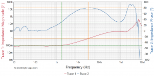 No_Electrolytic.png84.5 KB · Views: 323
 -
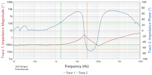 10uF Sprague Polycarbonate.png69.1 KB · Views: 316
 -
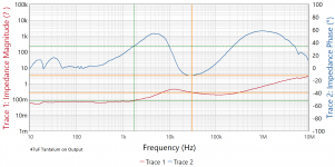 47uF Tantalum.png66 KB · Views: 317
 -
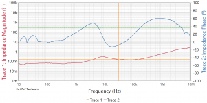 2x47uF Tantalum.png66.5 KB · Views: 270
 -
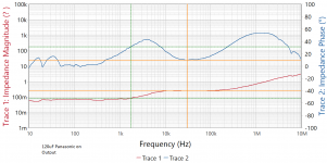 120uF Panasonic on Output.png65.4 KB · Views: 108
 -
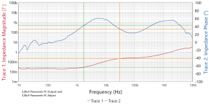 120uF Panasonic on Output and Adjust.png67.2 KB · Views: 105
 -
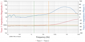 1000u_Aluminum_Electrolytic.png65 KB · Views: 111
 -
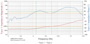 1000u_Plus120_Electrolytic.png67.5 KB · Views: 103
VERY cool! Thank you! Now, how 'bout noise/ripple graphs with the same combinations?Some impedance and phase graphs:
VERY cool! Thank you! Now, how 'bout noise/ripple graphs with the same combinations?
Noise you can see on Jan's website. The LM317 isn't remotely in the same class, by 60dB, as a super-reg. Not even worth discussing.
Bypassing the ADJ pin reduces the LM317 gain to unity. Therein lie the problems with it's imposition of harmonics on the supply rail.
To a first approximation you can regard the output of a regulator (almost any series regulator) as consisting of:
a DC voltage source
a noise voltage source (mix of white noise and ripple etc.)
a series inductance (possibly with a resistor across it)
a series resistance
Add a capacitor to this and you have a low pass filter, but potentially one with a high peak near the corner frequency. The peak is a peak in both noise and output impedance. You get to choose where in the spectrum you want this peak to be.
Look at the regulator output cap as a shunt frequency compensation (which it actually really is, from a small AC signal perspective). Then, it is easy to understand why a large capacitor would not create oscillation, the unity loop gain frequency will be very low and the phase doesn’t reach 180 there, but the stability comes to the price of the transient load response. It is also easy to understand why actually a ceramic nF range cap is the worst case from a stability perspective. It’s a very common beginners error to add a 100nF low ESR in parallel with the output electrolytic with a high ESR, hoping this will improve the HF performance; this is a safe recipe to get the regulator to oscillate. Very few integrated regulators will stay stable with a ceramic 10nF...100nF at the output, most require >1uF ceramic to stay stable.
A large output capacitor is a red herring; it doesn’t do anything good, but only potentially damages the regulator frequency response (although some electrolytics have a large enough ESR to look resistive at HF around the ULGF). It’s the filter capacitor at the input that plays the “reservoir” role.
My advice is to add at the output the minimum low ESR capacitor that unconditional stability requires. If the value is not in the data sheet, then experiment with, starting from 1uF and go up.
Very hard to read those graphs, dude. What Vin-Vout voltage are they done at? Doesn't the 33Ω resistor diminish the regulation?
The resistor is 0R33 and the input voltage is typically 18VDC. I was trying all and everything for fun. I was looking at the TL431 stability grahps and noticed very high or very low capacitance values are stable, the ones in the middle not. So I asked myself what about the LM317. I was delighted to find a small resistance made any capacitor possible. When I said zero ohms 1uF zero is subject to the lead impedance. If devices are surface mount it needs more care, assume a small additional resistor could help.
The final capacitor is not especially to help regulation, it will help. If you notice my hum graphs are not very good. 20 000uF before LM317 and 10 000uF after did nothing to change that. It was a slightly wrongly placed connection. That's a story in itself. The parts were what was at hand.
Below is what pleased me most up to this point. Notice how close the LM317 came and was if critical better. You most likely could remove a few capacitors. These are my notes to me and say" yes I did try that ". TL431 is not a device to try without a scope if wanting to try this. A CCS to the input terminal was no better. The output stability better than guessed. A single MJ3001 T03 darlington was almost as good and most likey would work without complications.


Here is the PCB version. The hum is now excellent and is almost identical with the PSU switched off. LD1084 extended the performance down to 200/100V, safely OK at 207V and 253V. As one can subtract 4% from 207V and still meet regs 198.72 was where I wanted to go. This PSU works to 2.2amps so losses are important. LM317 seems by measurement identical. The PCB was hard work. I had to hand etch crude versions before spending money. Years old chemicals put back to work. Dead Bug one was no trouble. I even recycled a failed PCB that never got etched. The first made with PVC tape and ferric chrolide that had set solid.
I don't read that in those graphs--the super regulators are definitely much better than the LM317, but by nowhere NEAR 60 db---more like about 35 db.Noise you can see on Jan's website. The LM317 isn't remotely in the same class, by 60dB, as a super-reg. Not even worth discussing.
Last edited:
That PSU of mine must be giving > -145 dB noise as it slams into the analyser limit. Now do a test of a 24 bit signal. I doubt it gets close to - 66dB if using real signals. The warning with super regulators is they might be a Mount Everest if you don't have test gear. As Plain Janes go LM317 can be made to be Beautiful Jane.
The maths I use is 21.6 dB ( 12 V ) + 111 dB ( analyser limit ). 0R33+10000uF is > -20 dB @ 500 Hz. The latter is conjecture except using theory of additive noise. If the two were equal we might see circa - 109 dB. I didn't. It seems resonable to think the filter was working. I got -89.5 dB ripple rejection, One has to guess the output reservoir gave 30 dB. Any battery I tried was worse, even hum was no better!
It's a shame I didn't use 35 V output. It that might have given me 142 dB range. Some would question the absolute reliability of that. I have use of an Audio Precission Analyser ( 2 in fact ). When I have compared the results they are not vastly different and usually within the maths. As NASA told me, Newton got them anywhere in the Solar System and Einstein was not required. I can't give you any of the AP data alas for reasons you might guess. At Harwell in the UK they have an external business dept. They must to complete a project use off the shelf solutions. One project was to make an advanced lens cleaner. Alas a common house cleaning product was 1/3 the price and equal. I always do the same.
My test gear came from the man who possibly designed your phone processor ( when he hung up his boots ). He has a Morris Minor car and lives near Cambridge. That chip cost about $100 000. Not all thinghs cost a fortune that change the world.
This is good reading if you like the Mount Everest route.
Op-Amp Based Linear Regulators
I have a hunch this is worth a try ( I have no values to offer ). There are various theories on zeners so two shown. This is the very idea I was told in 1973 not to bother with. Mostly that was right. The compound pair has been common since 1957. A 2N3055 in 1973.

Op-Amp Based Linear Regulators
I have a hunch this is worth a try ( I have no values to offer ). There are various theories on zeners so two shown. This is the very idea I was told in 1973 not to bother with. Mostly that was right. The compound pair has been common since 1957. A 2N3055 in 1973.

I don't read that in those graphs--the super regulators are definitely much better than the LM317, but by nowhere NEAR 60 db---more like about 35 db.
Without Cadj the noise of an LM317 is about 20dB higher.
Trade-off transient performance vs noise.
- Home
- Amplifiers
- Power Supplies
- LM317 load capacitance