yesOn the LM317 application notes, they show a 1uF capacitor on the output. Is that what you are recommending?
I built some 317 337 regulators recently and found this article very useful
Using 3-pin regulators off-piste: part 1
I built 2 stage regulators with diode protection - Used zeners and LEDs to set the voltages instead of the lower resistor in the voltage setting resistive divider, which gives better performance at lower frequencies, and used a cheap 10uf hign esr capacitor on the output local to the regulator.
If you follow the article the circuit I used was similar to the last circuit used in part 4.
I have not measured what I built but I am very happy with the results when used in my DAC project.
Some helpful detail here - Simple Voltage Regulators Part 2: Output Impedance
THANK YOU!! That is exactly the sort of information I was seeking! Certainly not some snide remark about lists.
THANK YOU!! That is exactly the sort of information I was seeking! .
Linear Tech. recommends 1uF solid tantalum as an output bypass cap because of its high frequency esr performance. This is useful b/c the V regulators loop gain tapers off. Really big output caps cannot offer any performance compared to the devices negative feedback, plus they fail to deliver at extended frequencies when its needed most! Depending your application Re. wiring/ PCBs you might need more bypassing further away from the 3T Vreg.
That guys blog echoes the LM317 data sheet, not any new information. My National Semi. Linear data book had the best data sheet since they invented it. Not every LM317 is created equal .E.g. internal band gap designs with nearby pass transistors and semi-processes matter. I reckon Linear Tech's is better than most esp. since everybody and their brother offers them E.g. its a jellybean part. The data sheet numbers are not hard to meet, its the typical numbers and how tight your processes are.
BTW If you need better ripple rejection (unlikely) it's reasonable to cascade regulator devices. Perhaps a series plus a shunt part, rather than more low pass filtering using BFcaps!
Last edited:
I'm curious, If I want to lower high frequency noise, is it helpful to use 10R +470uf on the output near op amp side?
So the HF noise I have to reduce will be emi,distortion from main, and LM317's thermal noise? Another question, if a op amp is 30Mhz, set gain as 10, so BW is 3Mhz, what should the power supply bandwidth be?
So the HF noise I have to reduce will be emi,distortion from main, and LM317's thermal noise? Another question, if a op amp is 30Mhz, set gain as 10, so BW is 3Mhz, what should the power supply bandwidth be?
Yes,getting rid of as much unwanted ripple and noise before the regulator is a good idea. I get how the capacitor(s) and inductor do just this. But how does the resistor help in this case? Seems to just eat heat and regulator headroom.I'd tend to agree with Wintermute to get rid of it upstream of the regulator. It depends how far you want to go...how small you want the ripple to be. Here's a LCR solution (an inductor is your friend) .
However, the ripple isn't pure 120Hz and contains a lot of HF hash. The LCR would definitely crush this.
The R in post 19?Yes,getting rid of as much unwanted ripple and noise before the regulator is a good idea. I get how the capacitor(s) and inductor do just this. But how does the resistor help in this case? Seems to just eat heat and regulator headroom.
Without it, the two C's and the L form a resonant circuit.
It also limits the inrush current to the second C
That kind of thing can bite you if the voltage regulated load is subject to steps in current drawn.
The optimum pre-filter in one application may be an own goal in another.
You make a fair point about regulator headroom. Sometimes you have to think about keeping everything working when the mains dips. Heat dissipated by the R was going to be dissipated by the reg anyway, for a given transformer voltage.
A wise man once said "return the noise from whence it came". This includes mains IEC filters , and ferrite beads and MLCC at signal entry / exits. Use snubbers at the switches / diodes, Use common mode chokes for SMPS , Class D power, etc.I'm curious, If I want to lower high frequency noise, is it helpful to use 10R +470uf on the output near op amp side?
1st you have to master the measurements before you can determine a solution.So the HF noise I have to reduce will be emi,distortion from main, and LM317's thermal noise?
There about 3 or 4 types of noise, usually thermal is least of worries.LM317's thermal noise
Bypass the references / bandgap before its multiplied up. Look into newer ICs that offer what you need, I have no idea what your application is. FWIW some VCOs and PLL charge pumps have the most stringent requirements, they have solutions if you look hard enough.
Use the signal BW after filtering. It's generally unwise to keep multi-MHz signal BW for audio Re internal noise and interferences. 'Audio Marketing' may have other ideas on the BW. LOLAnother question, if a op amp is 30Mhz, set gain as 10, so BW is 3Mhz, what should the power supply bandwidth be?
What is the magnitude and frequency of the PS ripple? Look at the devices app notes for guidance on IC power supply decoupling. Inserting a lossy series element often dramatically increases ANY bypass's effectiveness, use ferrite beads and/or low value R's. Once again it depends on your applications, The use of differential signals solves many potential system level pitfalls.
Last edited:
IMO, what's all wrong is to look for the ultimate PS for audio equipment.
I understand the search for the very best for a lab power supply.
However, for an audio equipment, it's PS is only a part of it.
In the case of too much hum, it's origin should be identified first and then the solution is either improving the equipment PSSR or PS ripple/load regulation whichever is easier.
It is non sense to keep a poor PSSR amplifier and spend time and money in search of a no ripple PS at any speed.
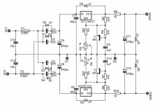
What do they power with this PS ?By the way,
what about this Elektor-approach?
It was provided for "THE PREAMP", 1986.
There is a big capacitor after the Regulator and a 10Ohm series resistor.
(redrawn by me)
What output current ?
The added 4700 uF can improve ripple ( cut off frequency is 3.5 Hz )
The added 10 Ohm ruins load regulation ( 10 Ohm )
The added transistors and associated rc are for a soft start.
Last edited:
Like what ?Those 10 Ohm resistors prevent a few issues")
As I wrote: "THE PREAMP", from 1986What do they power with this PS ?
take a google search: "elektor preamp 1986"
here you can see a pic:
http://www.analog-forum.de/wbboard/gallery/userImages/71/1160-7196dac4.jpg
don't know, I don't have this device, only the magazine, in which the building instructions were published.What output current ?
Right.The added 10 Ohm ruins load regulation ( 10 Ohm ) The added transistors and associated rc are for a soft start.
For a (other) preamplifier I built a PS like this with a modification. Line- / phono stages with largely constant current are fed by the "UPOS / UNEG", as indicated in the shown circuit. For other components that produce more and more variable current (relay, control lamps, etc.), I have provided further connections before the 10Ohm resistance.
- Home
- Amplifiers
- Power Supplies
- LM317 load capacitance