eBay has a cheap isolated smps to generate B+ from 12VDC with enough throughput for a substantial valve amplifier. This is a neat way for DIY to not require any AC mains wiring within an amp. A suitable mains plug-pack, with regulated 12VDC and enough current to suit valve heaters and this dc-dc, is all that is needed.
I just got two units in from:
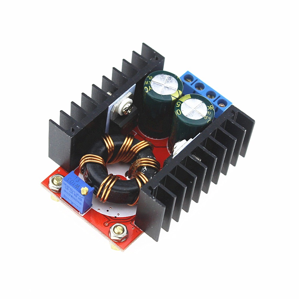
150W Inverter Boost Board Transformer DC-AC Converter 12V to 110V 200V 220V 280V | eBay
A recent thread was on the diodes in that power supply:
Suggestions needed for a diode to rectify 37kHz
The primary side uses a SG3525A controlled push-pull with a YP17575C fet each side on a heatsink. Can't find datasheet for the FET but it seems to be pretty good for the job. PCB layout is good for leaded parts. The secondary offers an isolated 0-110-200-220-280V winding/taps, and a full bridge of HER207 fast diodes.
A basic doubler using the 0-220V winding provides a simple means to generate approx 430Vdc for a PP output stage, as well as 215V for preamp stages, and suitable for a push-pull pair of any common valve such as 6L6GC etc., as the output power delivery seems to be fine for at least 60-100W.
A doubler allows two 300-350VDC small electrolytics to easily fit on the pcb -
I used 10uF which have sufficient ripple current capability (especially due to the 25kHz fundamental ripple - 50kHz as seen from the B+ output). The voltage rating needs to cover the maximum voltage that could be output - as the output voltage is unregulated, it will increase with module input voltage (so idle voltage could exceed 500V if the input dc exceeds 14V).
I removed the HER207 diodes, and the blue connector, and fitted 2x UF4007 on the rear for the doubler diodes, which gave a neat small switching current loop along with the electrolytics. There is no need for 'larger' or better diodes imho, and the capacitance of larger diodes will just add to switching losses.
The pcb pads for the HER207 diodes can be conveniently used for inserting some low value resistors, or inductors, to act as a balanced high-frequency filter with a shunt capacitor on the rear of the output terminals.
As I had some smt caps, I was able to easily fit them to minimise some switching current loop lengths, but its doubtful whether any noise would be noticeable (it would probably need a good spectrum plot of the final amp to detect).
I only had a 12Vdc 5A plug pack (12VDC 5A Desktop Power Supply - Fixed 2.5mm Plug | Jaycar Electronics) so just tested to 97mA 41.2W loading on 426V output, with 3.8A input.
No load loss within the dc/dc module is about 2.5W with 12Vdc input, and that loss increased to about 3.3W for 41W output - where FET heatsinks didn't rise by more than 2-3degC, and transformer winding outer surface was about 20degC rise.
If going this DIY path, then I recommend using a good quality AC smps plugpack with a protective earth pin that connects through to the 12Vdc output, as that then provides a protective earth path for the amp chassis, and the plugpack to have current limiting. As an example - the compliance file for my plugpack is https://www.jaycar.com.au/medias/sys_master/images/8998748520478/MP3242-dataSheetMain.pdf
I just got two units in from:
150W Inverter Boost Board Transformer DC-AC Converter 12V to 110V 200V 220V 280V | eBay
A recent thread was on the diodes in that power supply:
Suggestions needed for a diode to rectify 37kHz
The primary side uses a SG3525A controlled push-pull with a YP17575C fet each side on a heatsink. Can't find datasheet for the FET but it seems to be pretty good for the job. PCB layout is good for leaded parts. The secondary offers an isolated 0-110-200-220-280V winding/taps, and a full bridge of HER207 fast diodes.
A basic doubler using the 0-220V winding provides a simple means to generate approx 430Vdc for a PP output stage, as well as 215V for preamp stages, and suitable for a push-pull pair of any common valve such as 6L6GC etc., as the output power delivery seems to be fine for at least 60-100W.
A doubler allows two 300-350VDC small electrolytics to easily fit on the pcb -
I used 10uF which have sufficient ripple current capability (especially due to the 25kHz fundamental ripple - 50kHz as seen from the B+ output). The voltage rating needs to cover the maximum voltage that could be output - as the output voltage is unregulated, it will increase with module input voltage (so idle voltage could exceed 500V if the input dc exceeds 14V).
I removed the HER207 diodes, and the blue connector, and fitted 2x UF4007 on the rear for the doubler diodes, which gave a neat small switching current loop along with the electrolytics. There is no need for 'larger' or better diodes imho, and the capacitance of larger diodes will just add to switching losses.
The pcb pads for the HER207 diodes can be conveniently used for inserting some low value resistors, or inductors, to act as a balanced high-frequency filter with a shunt capacitor on the rear of the output terminals.
As I had some smt caps, I was able to easily fit them to minimise some switching current loop lengths, but its doubtful whether any noise would be noticeable (it would probably need a good spectrum plot of the final amp to detect).
I only had a 12Vdc 5A plug pack (12VDC 5A Desktop Power Supply - Fixed 2.5mm Plug | Jaycar Electronics) so just tested to 97mA 41.2W loading on 426V output, with 3.8A input.
No load loss within the dc/dc module is about 2.5W with 12Vdc input, and that loss increased to about 3.3W for 41W output - where FET heatsinks didn't rise by more than 2-3degC, and transformer winding outer surface was about 20degC rise.
If going this DIY path, then I recommend using a good quality AC smps plugpack with a protective earth pin that connects through to the 12Vdc output, as that then provides a protective earth path for the amp chassis, and the plugpack to have current limiting. As an example - the compliance file for my plugpack is https://www.jaycar.com.au/medias/sys_master/images/8998748520478/MP3242-dataSheetMain.pdf
Last edited:
At the 41W output loading, I had a bit over a 100mV sawtooth ripple on 12Vdc input, but I was using a standard 100:1 probe with ground lead so signal was a bit noisy. I checked for output ripple on my Kiethley 197 on AC and lowest 200mVac range and the ripple/noise was 'low' but not reliably measurable, but would have been well below 100mVrms. I didn't put the CRO probe on the output, as I was a bit reluctant to damage my $1 USB soundcard interface 
I've used these many times, usually at 280V for HP/Phono/Preamp service. I also use the 220V AC output with UF5408 doubler to run the Williamson front end of a power amp.
It will fail prematurely if you use a large choke on it's output, and the weak point is the transformer.
A better choice for running power amplifier would be it's big brother at 500W.
MINI DC-AC Inverter 12V to 18V220V/380V 500W Boost Step UP Power Module New Hot | eBay
I am using one of these to power PP 6P3S, using a disassembled ATX power supply for the 12V.
There is also this one: DC-DC 8-32V to +-45V-390V Step-up ZVS High Voltage Capacitor Module Charge Board | eBay
Adjustable output, regulated, however not isolated. I use these in Phono amps. it's Bipolar, too.
Cheers.
Last edited:
In my case the transformer windings got hot enough to melt and short. Haven't had the problem since I stopped using a 4.5H choke input filter. And I use UF5408 or HER208 now. I've also had a failure from the MOSFETs getting too hot. The heatsinks reached over 95c.
Generally I de-rate them to less than half of the stated output power. The 150W inverter is good for about 70W without a fan in 50c ambient temperature.
Generally I de-rate them to less than half of the stated output power. The 150W inverter is good for about 70W without a fan in 50c ambient temperature.
Thanks for adding that info. I'm interested to get more of an understanding of your experiences if you don't mind the queries
Was the '4.5H choke input filter' actually a circuit with the UF5408 diodes rectifying directly in to the choke without any local filter capacitor buffer (ie. a CLC filter arrangement) ?
I could hardly detect a temperature rise on the FETs when pushing out 41W with a 12Vdc input. For your '95C' situation, were you pushing through a lot more power, or operating with a different input voltage, or using the choke output filter or?
I was using the DC output of the boost converter (green screws) using the stock HER207 rectifiers, into a 6Z4 tube (both halves in parallel) into the 4.5H choke into 100uf into the load.
The ambient case temperature of the preamp it was inside was over 50c. I also find the choke filter causes the adjustable ones to oscillate. It was powered from an SMPS set to 12.6VDC. It will put out more power and run cooler with a fan obviously but I want a silent supply for audio Nobody wants to hear fan noise, right? Is your module the new revision (there is a diode soldered to the back of the board)? I had issues only with the older version without that diode. I see yours uses different MOSFETs... Mine uses a generic Chinese version of the IRF3205.
The ambient case temperature of the preamp it was inside was over 50c. I also find the choke filter causes the adjustable ones to oscillate. It was powered from an SMPS set to 12.6VDC. It will put out more power and run cooler with a fan obviously but I want a silent supply for audio
Nobody wants to hear fan noise, right? Is your module the new revision (there is a diode soldered to the back of the board)? I had issues only with the older version without that diode. I see yours uses different MOSFETs... Mine uses a generic Chinese version of the IRF3205.
Last edited:
Strangely, of the 2 units I purchased, only one had the extra protection diode clamp!
I would certainly recommend never to use a choke input filter with such a smps, and suggest that that would be a key issue with some of your failures/stressed units.
Smps like that should imho aim for the smallest loop rectification and capacitance filtering.
I would certainly recommend never to use a choke input filter with such a smps, and suggest that that would be a key issue with some of your failures/stressed units.
Smps like that should imho aim for the smallest loop rectification and capacitance filtering.
I bought a couple of these (shown in the 1:st post) for HV to battery feed a tube radio and found the transformer was almost saturated at 12.6VDC input. At 14VDC it saturated heavily and also the ’dead time’ was factory set to around 20% of a cycle!!....?
As i think there is a miss in the design and the switching frequency for the transformer is to low at the measured 25KHz switching frequency.
So I changed the 5600pF timing capacitor to 3000pF and the ’dead time’ resistor from 200 Ohm to 27 Ohm. The timing resistor 4.3 KOhm beside is not changed.
The oscillator now runs at 102KHz and the transformer at 51KHz and there is no saturation problems up to over 16VDC input. The transformer also runs much cooler now and the supply is very smooth and stable with just a 22uF capacitor at the output.
You must observe that it is a bridge rectified full vawe push-pull, full duty-cycle square vawe output from the transformer, so there is very little rippel with just a capacitor. Just have to smooth out the glitches of the now much shorter ’dead time’ (from 20% to around 3%)
The stray field from the transformer and ringings are also much less now.
I will make further work to modify the zobel network over the primary, to dampen the remaining ringing even more. Maybe need 2 zobels to make it perfekt, one over each primary as there are some residual ringings in the leakage inductance between the 2 primary windings.
For references and more, look up and check the datasheet for the SG3525
Johan
Johan, can you elaborate on how you identified the transformer was being saturated at 14Vdc?
I'll check what timing part values are on my 2 units, and if I recorded loss measurements at higher than 12Vdc input.
I was just able to identify a datasheet for the YPI 7575C fet used in my modules - they are 70V 85A rating (YPI7575C ???MOS? - ?? - ????) - so interesting to see how close your Vds gets to 70V.
Johan, can you elaborate on how you identified the transformer was being saturated at 14Vdc?
I'll check what timing part values are on my 2 units, and if I recorded loss measurements at higher than 12Vdc input.
I was just able to identify a datasheet for the YPI 7575C fet used in my modules - they are 70V 85A rating (YPI7575C ???MOS? - ?? - ????) - so interesting to see how close your Vds gets to 70V.
First I hooked it up to a variable bench DC supply and checked the idle power consumption with no load and found it rising quickly above 12VDC input.
The transformer core also heated up at idle and gave over-shoot that was peak rectified in the diode bridge. The output voltage was not following the input voltage, but rised fast to over 600V.
By increasing the switching frequency the transformer works much more efficient and don’t get near saturation.
I think the designer made the misstake to set the SG3525A oscillator to 50KHz and thinking that was the switching frequency. But that frequency is halfed in the output drivers to 25KHz......I’ve seen others do that misstake too with the excellent 3525.
At higher switching frequencies the slew rate gets little less steep due to the input capacitance of the MOSFET’s (thanks for the datasheet, I was searching for 17575C.......) but that will not conciderly increase the losses.
I noticed in an other thread about this inverter, the TS stated 37KHz switching frekquency, but I measured truly 25KHz on my counter (and as the TS stated in the headline of this thread), so maybe the manufacturer has uppgraded the desing and my samples was from older stock at the distributor......
I noticed there is a big brother to this inverter with double MOSFET’s and this put more strain on the outputs from the 3525. Some designers use an extra transistor driver circuit to drive the pairs......
The 7575C seems to be a very good choise in this converer and runs very cool due to the low 6.5 mOhm on resistance.
The 70V rating is normal for auto-motive use and absolutely OK for this use, as the voltage will not exceed the battery voltage 14,5VDC + transients in a running car, during alternator charging.
The 7575C is probably designed for general automotive use.
As I will use my converters to run HV+ on tube shortvawe radio receivers, I’m very keen to supress all unwanted high frequency spurious signals from the converter!
Yes I now see they have stated the switching frequency to 37KHz in the specifications, so owners with a measured 25KHz should alter the oscillator frequency to at least 75KHz to make the inverter to run smoth.
150W DC-AC Inverter Boost Board Transformer 12V to 110V 200V 220V 280V Converter 665995358378 | eBay
150W DC-AC Inverter Boost Board Transformer 12V to 110V 200V 220V 280V Converter 665995358378 | eBay
- Status
- This old topic is closed. If you want to reopen this topic, contact a moderator using the "Report Post" button.
- Home
- Amplifiers
- Power Supplies
- '150W' 12VDC isolated 25kHz step-up smps for B+