Hi guys,
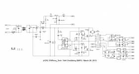
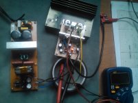
I am confused with my diy smps behaviour, you see it is working fine if I use IGBT but if I swap them with the 2sk toshiba devices, the AC mains lamp bulb limiter lits and I don't get any dc reading at the secondary out. Using a 100w bulb load (output traffo disconnected) it oscillates, the test bulb lits.
Can anyone suggest a workaround solution so I can use the toshiba devices? My IGBTs was intended for other DIY projects.
Thanks!
Albert
Attachments
1.3 ohms rdson is quite high maybe the SMPS is thinking the current is too high with the mosfet and is turning off ?
That could be another part of the problem, but I'm not quite knowledgeable working with smps, I tried changing the value of feedback resistor (1k series with 470pf) possibly to shift working frequency? Nothing positive changes made except making the fets more warmer.
This sounds like oscillation at a much higher frequency than intended: the MOSfets have a much larger bandwidth than the Igbt's and are probably trying to oscillate (very inefficiently) at RF frequencies.
You could try to slow things down by paralleling a capacitor with the 100t winding of the FB transformer.
Value should be chosen to resonate with the winding's inductance at ~10 times the intended switching frequency. A damping resistor in series might be required to suppress other unwanted behaviors (a few ohms to tens of ohms)
This sounds like oscillation at a much higher frequency than intended: the MOSfets have a much larger bandwidth than the Igbt's and are probably trying to oscillate (very inefficiently) at RF frequencies.
You could try to slow things down by paralleling a capacitor with the 100t winding of the FB transformer.
Value should be chosen to resonate with the winding's inductance at ~10 times the intended switching frequency. A damping resistor in series might be required to suppress other unwanted behaviors (a few ohms to tens of ohms)
Hi Elvee,
I am thinking of rewinding the gate drive traffo, perhaps lowering the no. of turns will it also work? I saw some design that uses a toroid of about 10-20mm diameter with around 12t of wires for the primary and secondaries (ratio 1:1:1). Just do not know about the material used.
Maestro Elvee,
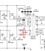
I noticed in comparison with the original schematic from Detex Audio, the schematic at first post does not include these. (attached image). Schematic at first post is a scaled down version using 2 fets, the attached image uses 4 fets. I extracted these datas to compare with the fets devices used.
IRFP460 (used originally)
RDS(on) 0.27r
Input capacitance 4200pf
Output capacitance 870pf
Qg 210
Qgs 29
Qgd 110
(values in nc)
2SK2746
RDS(on) 1.3r
Input capacitance 1500pf
Output capacitance 140pf
Qg 55
Qgs 30
Qgd 25
Will this scheme will work out too in the first schematic?..perhaps doubling the values?
Attachments
Thanks for the title of maestro, but if you look for one, you should search elsewhere. Eva for instance, if she deigns to have a look at your problem.Will this scheme will work out too in the first schematic?..perhaps doubling the values?
In the mean time, I think that the snubber is a good idea: try first with the original values and if you notice an improvement, you can tweak it further.
If you use too aggressive values, the dissipation will become unbearable
Thanks for the title of maestro, but if you look for one, you should search elsewhere. Eva for instance, if she deigns to have a look at your problem.
In the mean time, I think that the snubber is a good idea: try first with the original values and if you notice an improvement, you can tweak it further.
If you use too aggressive values, the dissipation will become unbearable
At the solid state forum you are a Maestro
") I will do some work on the PCB so I could fit in the snubbers, and find out how it goes.
I will do some work on the PCB so I could fit in the snubbers, and find out how it goes.Sa muli,
Albert
Attachments

While hunting for a suitable gate drive traffo for the 2 fets version..I built Acca's bjt version, tested it in my P3A build (one channel)
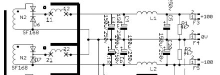
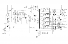
Meanwhile I want to see your opinion on this other smps circuit that I googled around. I got interested in the secondary diode config. because it only uses 2x 3pin diode to get a split output supply (+/-100vdc in the schematic). I tested it using a discarded 12-0-12vac traffo, but surprisingly I got a split +/-6vdc reading. Measuring across on both ends of winding I get +12vdc. Is this correct?
Regards,
Albert
Attachments
- Status
- This old topic is closed. If you want to reopen this topic, contact a moderator using the "Report Post" button.
- Home
- Amplifiers
- Power Supplies
- Self-oscillating SMPS problem