Hi all
Not sure if anyone might be able to help me out here.
I'm in the process of refurbing my two Maplin 100w Mosfet amps that I built back in 1982, Actually probably more like 75w as they use the 2SK133 and 2SB48 pair.
These two little amps served me very well for many years during the 80's and early 90's as a stereo Hi-Fi amp, driven from the pre amp of a Trio KA-305 and into a pair of Goodmans Magister Loudspeakers (15" Bass Speakers).
Later on in the mid 90's the amps were removed from their case and put into a Stereo Combo amp which I built for my keyboards for use when I joined a band for several years.
The amps remained in the combo until 2010 (and were still working well) when I needed to make some space, so striped the combo, sold the 2 Mckenzie speakers, threw away the Smoothing Caps because of their age and put the amps and Transformer into a plastic storage box where they have remained until now.
On a side note, I have seen quite a few people had problems with hum and noise, I must have been very lucky, I had no such problems, when they were being used for Hi-Fi they were whisper quiet, only a very gentle bump at switch on, and if you put your ear against one of the speakers the only noise was a faint Hiss from the tweeters.
So a bit of background there ..
The main question as in the title, I need some help in identifying the Toroidal Transformer, It's made by ILP in the UK, and the part number or Type number is 72018.
The secondary voltages are 2 x 37.5v, but I have no idea what the current rating of each secondary is, although I'm fairly certain that when I built it I would have allowed enough headroom to be able to cope with both amps at full power, or maybe not !! Looking at Toroids with similar dimensions 110mm Dia and 50mm High it looks like it might be a 225VA.
So if anyone can or has any information on this transformer I would greatly appreciate it, as it will help choosing new Smoothing Caps with adequate Ripple Current Rating.
Thanks In Advance.
ILP used the winding wire as leadouts.
Measure the wire diameter and using 3A/mm^2 gives you a good guide to current rating.
Primary windings :
0.8mm diam ~ 1.5A ~350VA, 0.7mm diam ~ 1.2A ~275VA, 0.6mm diam ~ 0.9A ~200VA
Secondary windings:
1.4mm diam ~ 4.8A ~340VA, 1.3mm diam ~ 4A ~280VA, 1.2mm diam ~ 3.5A ~245VA, 1.1mm diam ~ 2.9A ~210VA
For a 225VA & 250VA you are likely to find 0.7mm & 1.2mm
It will not be 37.5Vac,
They made 230:35Vac
In both dual primary dual secondary and single primary dual secondary.
I saw a data table some years ago for the ILP range. Did a quick search just now and found nothing.
You don't need the transformer data to select smoothing capacitors.
Your load and the duty you intend imposing on the amplifier determines your smoothing requirements.
Last edited:
Maplin recommended a 300V/A for a pair of 100W amp kits at 35volt twin secondaries.
Toroidal Transformers | RS Components
is a good place to start.
Smoothing was 4k7uF per rail per amplifier so 10kuF 63v will be ideal.
Aluminium Capacitors | RS Components
Toroidal Transformers | RS Components
is a good place to start.
Smoothing was 4k7uF per rail per amplifier so 10kuF 63v will be ideal.
Aluminium Capacitors | RS Components
Rails +/-55V. (39-0-39V AC secondary, 10,000uF + 100nF/rail off-board smoothing recommended)
Setting up - Meter in +V rail, adjust RV1 to 100mA idle current. DC offset should be below 50mV, over 0.5V = fault. Check zobel resistor R15 is not
hot = oscillation.
Specification: 20Hz - 40kHz, THD 0.01% @ 1kHz, 100W/8R
From 'Electronics - The Maplin Magazine' No.41, Dec'90-Jan'91
Setting up - Meter in +V rail, adjust RV1 to 100mA idle current. DC offset should be below 50mV, over 0.5V = fault. Check zobel resistor R15 is not
hot = oscillation.
Specification: 20Hz - 40kHz, THD 0.01% @ 1kHz, 100W/8R
From 'Electronics - The Maplin Magazine' No.41, Dec'90-Jan'91
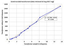
I recall that Bob Cordell's power amplifier book suggested that one way to estimate the Volt-Ampere capability of a transformer is: weigh it! He gave a rule of thumb value
such-and-such number of volt-amps, per kilogram.
Sorry I don't know the page number; a super motivated individual might quickly read through all sections that discuss power supplies, and find it.
such-and-such number of volt-amps, per kilogram.
Sorry I don't know the page number; a super motivated individual might quickly read through all sections that discuss power supplies, and find it.
Anybody who wants to learn more, can visit transformer manufacturer's websites and find data for VA ratings and weights. Then simply type the data into Excel and find out whether or not the data exhibits a straight line relationship.
To show that I'm not a lazy person (this morning!), I did so on the website of Antek Inc. My results are below.
Those who distrust linear regression can, of course, eyeball-interpolate between entries in their data table.
_
To show that I'm not a lazy person (this morning!), I did so on the website of Antek Inc. My results are below.
Those who distrust linear regression can, of course, eyeball-interpolate between entries in their data table.
_
Attachments
Last edited:
Thank you all for your replies.
Interesting about the voltage, I measured the secondaries off load, with two DVM's, on being a True RMS meter and got around 37.48 from one winding and around 37.6 on the other, this may well drop to nearer 35v once connected to the Bridge Rectifier,Smoothing Caps and amps at idle.
I just took a quick measurement of the Secondary Wire Diameter with a digital vernier, and its bang on 1.3mm, so can assume its a 280va, Maybe just a tad underated for both amps, but for Hi-Fi Use the combination never gave me any problems volume wise.
As for Caps, I was thinking of 2 x 6800uf 63v per rail, seems like solder tag types are just about obsolete these days, with Snap Fit being the norm for this Value and voltage, there are the screw terminal types but I would prefer a soldered connection.
I had been looking at some Vishay Caps on ebay, and looking at the data sheet, they have a ripple current of 3.3A, so two in parallel should double that to 6.6A as far as my understanding goes? Given that the Transformer has an apparent current of 4 amps, I would really like to see the caps with 8 amp or greater ripple current, so am a bit torn between using a bunch of smaller caps, or go with a single 10000uf cap per rail with a ripple current rating of around 9+ amps, What do you guys think?
Regarding the Bias setting, I for some reason seem to recall this was set as stated above, but without a load on the output? ...... So long ago, wish I had kept the original article which I believe was published in the Maplin Magazine !
I have a Rigol DSO so can check for any oscillation or abnormalities during setup, although I don't really see any problems as I shall only be replacing the electrolytic caps and replacing the thermal paste under the Mosfets.
BTW The transformer weighs in at 2.43kg
Last edited:
I have an old ILP data sheet. The type No. is 7A018, 35+35 volt, 300VA. The primary for this transformer is 117 VAC.
Don't know if 72018 is a 230 VAC primary.
Hope this helps
Hi, and Thank you, That's very interesting, the 72018 is indeed a 230v or UK Voltage single Primary Transformer, and if the 018 part of the code means 300VA then that's very good news, I thought it strange that I might have fitted an under rated Transformer.
I have been searching for the Data Sheet for the last few days, but drawn a blank.
Thanks again for your help.
Well, I'll be ......... I don't know how I missed this on my original searches !
Toroidal Transformers | ILP Transformers Unirange
Browse to the 7UR Series (300va), and the 7UR36 output voltages Vs Input voltage. This could well explain why I measured 37.5v on the secondary outputs, the Mains voltage here Rarely drops below 240v, and at this moment in time my UPS is displaying 246v, and it's not unusual to see it as high as 250/5v.
The weight of these transformers also corresponds to the same weight as the Transformer I have.
looks like the 7 tells us it's size, in this case 300VA
the 2 is maybe the code for the primary.
018 will be the secondary code, in this case dual 35Vac.
You measure the rated output voltage by supplying the rated voltage to the primary and applying the rated load (pure resistance, no rectifier, no capacitor/s).
For a 35Vdc 300VA transformer the rated resistance will be two off 8r167, each dissipating 150W
A 300VA toroid is likely to have a regulation of somewhere around 5% to 7%.
For this example calculation I'll assume transformer regulation is 6%
Output voltage maximum = Mains supply voltage / Rated primary voltage * Rated secondary voltage * {1 plus regulation}
Voutmax = 246/230*35*1.06 = 39.7Vac
Last edited:
 ) I will incorporate it into one of my many Excel Spread Sheet Calculators.
link to data sheet this may help
http://davidmager.co.uk/index_htm_files/ILP transformers 2 .jpg:D
http://davidmager.co.uk/index_htm_files/ILP transformers 2 .jpg:D
I have had trouble with hum on the output of the Maplin mosfet amps.
But, it would depend on how well the power supply was smoothed.
I have designed my own amps that had the same problem until I decoupled the front end of the amp from the output stage.
I have the original Maplin article on their 75WRMS mosfet amp but the transformer is only a couple of amps and 32-0-32 so is not the transformer you have.
- Status
- This old topic is closed. If you want to reopen this topic, contact a moderator using the "Report Post" button.
- Home
- Amplifiers
- Power Supplies
- Can anyone help me identify this Toroidal Transformer please?