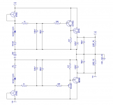
I made schematic of a Zener follower after reading post from Alciad
http://www.diyaudio.com/forums/chip-amps/49619-opa549-gainclone-layout-8.html#post587354
I am not sure if my design is correct. I used BF862 as current source in my schematic. J511 is FET current source and hard to source.
Please help me out by correcting this schematic.
http://www.diyaudio.com/forums/chip-amps/49619-opa549-gainclone-layout-8.html#post587354
I am not sure if my design is correct. I used BF862 as current source in my schematic. J511 is FET current source and hard to source.
Please help me out by correcting this schematic.
Attachments
Last edited:
When I looked at the data sheet on the BF862 at least to me it looks like it would
be a poor choice for a ccs. Especially like you will be using it in your circuit where you will have less than 3v VDS. I would think a simple resistor would work better here than that device. I think you may want to look at figure 8.file:///C:/Users/Woody/Downloads/datasheet.pdf
be a poor choice for a ccs. Especially like you will be using it in your circuit where you will have less than 3v VDS. I would think a simple resistor would work better here than that device. I think you may want to look at figure 8.file:///C:/Users/Woody/Downloads/datasheet.pdf


Simply PaintKetje,Thx!
Just curious how did you make changes to the schematic so fast? Or is it something you already made and using?
")
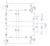
That's ok, chose for Idss= 5...10mA and a knee voltage not to high. Little mod on the output gives 0.6V more room for the fet.I was not sure if I was connecting the pins of JFEt right to use as current source.Please check for me.
Mona
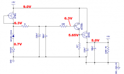
You need a reference voltage of 6 volts + Vbe.With a diode + zener the zener has to be 6volt.But 6volt zener isn't easy to find.A 5.1volts is , + 1.5 from a LED =6.6V. As long as the total LED (or an other voltage dropper) + zener = 6.6 volts you get 6 volts out.Thanks Mona. I also noticed you changed the 1N4148 with an LED. What is the reasoning behind it?
What are the specs of LED or is it not relevant?
Mona
Make sense.
Still could not figure out this part.
Still could not figure out this part.
Also will you be kind enough to explain why you picked 2N5459, for my learning purpose.Little mod on the output gives 0.6V more room for the fet.
Mona
Well, it goes like this.Probable other (better) ones to find, didn't look furtherAlso will you be kind enough to explain why you picked 2N5459, for my learning purpose.

Mona
Attachments
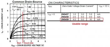
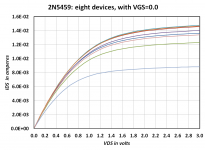
Attached below are the IDSS curves of eight JFETs that happened to be rattling about in my parts box. There are within spec but a little on the high side; somebody else must have gotten the shipment of low-IDSS parts I suppose. Feel free to eyeball-extract the incremental resistance at VDS=2.4 volts if you wish; take the slope of the tangent line and recall that r = deltaV/deltaI. I get 1.6Kohms but might be mistaken.
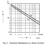
Line Regulation (= deltaVout / deltaVin) at DC is set by a simple voltage divider, whose pullup is the JFET incremental resistance, and whose pulldown is (Zener incremental resistance + 1N4148 incremental resistance). Vishay's datasheet suggests that the zener is 20-30 ohms, and LTSPICE suggests that the 1N4148 is 2.6 ohms.
So if Rpullup=1600 and Rpulldown=27.6 then Line Regulation is -35 dB. Or thereabouts.
_
Attachments
Set Vin = 9.0 volts. Measure Vout.
Set Vin = 9.1 volts. Measure Vout again.
Then "Line Regulation" = (Vout2 - Vout1) / (9.1 - 9.0).
I estimate that with a 2N5459, 1N4148, and BZV85-C5V1 as shown in post #1, your circuit's Line Regulation will be no better than (27.6 / 1627.6) = 1.70% = -35 dB. Replacing the 1N4148 with an LED will make Line Regulation slightly worse because the incremental resistance of an LED is higher than the incremental resistance of a 1N4148.
For every volt of change on Vin, your Vout will change approx. (1.70% of 1V) = 0.017 volts.
To put that in perspective, the Fairchild uA723 integrated circuit voltage regulator came out in 1972; its Line Regulation was 0.1%. More modern voltage regulator ICs have Line Regulation specs that are 100 times lower.
But you might be perfectly happy with what you've got here. It's your decision, nobody else's.
- Status
- This old topic is closed. If you want to reopen this topic, contact a moderator using the "Report Post" button.
- Home
- Amplifiers
- Power Supplies
- Zener+Voltage follower