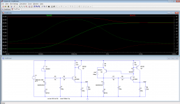
To improve the line regulation, you can use this simplistic fix: just replace the jFET CCS with a banal BJT CCS, and you gain 40dB of static line regulation.
The higher frequency behavior remains unchanged because ultimately it is dictated by the Early effect of the transistors.
Note that this mod will also greatly improve the load regulation.
R10 is required to make the circuit start by itself, but it degrades the performances only very slightly
The higher frequency behavior remains unchanged because ultimately it is dictated by the Early effect of the transistors.
Note that this mod will also greatly improve the load regulation.
R10 is required to make the circuit start by itself, but it degrades the performances only very slightly
Attachments
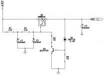
It is also possible, but it is less advantageous: when placed over Q3, you need it to make it low enough to overcome the direct voltage of D5, and diodes tend to have a much higher saturation current than the emitter junction of a small transistor like Q5.
By contrast, if you place it across Q5, you only have to overcome the leakage current of the zener under near-zero volt bias, and then you benefit from the β of Q3 to overcome D5.
In this example, the maximum resistance required for startup is 10MΩ across Q3, and 3GΩ over Q5, but there are additional factors making it more advantageous: the relative perturbation is the ratio of the parasitic current to the standing current, which will be higher for the zener than for D5, and in the case of D5-Q4, the perturbation to the base current will remain unmitigated during normal operation whereas it will be accounted for in the CCS current Q5 because the resistance is returned to R9 rather than +Vin
Note that the actual difference between the two methods is extremely small anyway: here, less than 2dB for the maximum resistances, which is peanuts compared to ~92dB
Last edited:
In theory, yes, but in practice it would probably not be an issue, except perhaps with micropower circuits: if you use the maximum possible of 10MΩ, the regulation would be lost at around 300nA, probably low enough to be provided by the leakage of C4.
And if it doesn't suffice, you could always add a "bleeder" of 15MΩ
In the same vein, the other circuit may well start correctly even if R10 is absent: 3GΩ is quite large, and various leakages could allow for a spontaneous startup.
However, it is better to use an explicit resistor, even if it is 22MΩ: it will be more deterministic
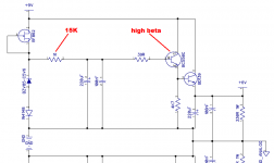
For lowest noise you want to filter the zener diode HARD, i.e., a very low corner frequency for the RC filter.
Fortunately you have chosen the high beta BC550-BC560 devices as the first stage. This is good because high beta reduces base current. Low base current is good because it lets you increase the base resistance. LTSPICE says your 1K base resistor has 3-4 uA flowing in it. I suggest changing this resistor to 15K instead of 1K.
If your PCB and budget can tolerate the change, I suggest also changing the 220uF capacitor to 1000uF. More bigger is more better.
_
Attachments
Since the limiting factor (as in simple capacitor multipliers) stems from the Early effect, improving the filtering is unlikely to lead to improvements in the output, and in fact, using a high beta transistor is not only unnecessary, but will harm the PSRR even more: the beta and Early voltage bear an inverse correlation.
I have analyzed the effect and even proposed a cure, it is probably in this part of the forum, somewhere
I have analyzed the effect and even proposed a cure, it is probably in this part of the forum, somewhere
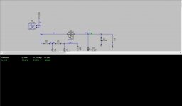
I use this circuit for my germanium headphone amp, set up for 12 volts instead of 6 here. Second gives an example of ripple rejection loaded down to 100ma. Works well for me.
Attachments
Last edited:
Here are some measurements of zener noise: (link)
Squirt that through a lowpass filter with the same corner frequency as used in your power supply, and presto you get the component of the output noise that came from the zener. If you also want to know the component of the output noise that was passed through from a noisy 9V input to 6V output, then you'll have to do a more thorough analysis and/or simulation.
Squirt that through a lowpass filter with the same corner frequency as used in your power supply, and presto you get the component of the output noise that came from the zener. If you also want to know the component of the output noise that was passed through from a noisy 9V input to 6V output, then you'll have to do a more thorough analysis and/or simulation.
I imagine you meant C=10mF=10000µF and L=40mH=40000µH
In this case, the input noise will be ~100µV rms. This ripple will be attenuated by ~50-60dB, resulting in a 0.15µV output noise.
At the lowest audio frequency, say 16Hz, the zener noise will be attenuated by ~27dB by the RC filter.
If it is ~3-4µV at that frequency, its contribution will also be around 0.15µV.
Improving the filter will therefore have some effect on the output noise, but it will be marginal, in fact more marginal than that, because a lot of noise will be higher in the spectrum, where it will be attenuated more efficiently by the existing filter.
Increasing the cap to 470µF might be sensible, but going higher makes no sense unless you fix the PSRR aspect, which is going to be difficult whilst keeping things simple
The 1K + 220µ after the zenerWhich one you refer to as existing filter ?
The original circuit will work properly, even if its output voltage is not exactly spot on.I am wondering if someone can summarize the finding
The first mod proposed by Ketje will be more accurate, and will also work better.
The mod I proposed will improve the line regulation, but I am not sure you need that: looks more like a bell or whistle, if you fancy them.
But that mod also has less obvious benefits: it frees you from using a FET which, even if you can source it easily could be advantageous: even sorted FETs, with a letter suffix or a color typically have 1:2 dispersion on parameters, like Idss meaning the zener current will be very loosely defined.
The BJT CCS is much less dependent on such primary parameters, giving a more consistent zener current.
The load regulation will also be improved, should you need it, and somewhat perversely, the performances will tend to be even better with a smaller filter capacitor, because of the error-correction nature of the topolgy, combating the inherent Early effect.
I wouldn't count too much on that though, as a full correction would need some work to ensure matching, but at least, a first order compensation going in the right direction is present, which is good.
Anyway, the main source of noise appearing at the output will most likely be caused by the input ripple, -mainly-.
Your zener would need to be really noisy to exceed that.
However, since capacitance costs nothing nowadays, you can use 470µ instead of 220µ, just to be sure. More of brute force wouldn't help in any way, because the floor will be set by the Early effect, which is difficult to combat with simple means in such simple topologies.
You could always use a better transistor in this respect than the BC550, but you won't go very far.
My topology can correct for that, but for really high rejection, you would need serious matching measures (and forego the largish capacitor).
In all cases, you should end up with an output noise <1µV, which any non-pathological circuit you connect it to should tolerate easily, meaning you are more or less free to chose whichever option you like most
- Status
- This old topic is closed. If you want to reopen this topic, contact a moderator using the "Report Post" button.
- Home
- Amplifiers
- Power Supplies
- Zener+Voltage follower