Most amp projects incorporate an internal PSU with a rectifier bridge or discrete diodes. We then sometimes add noise capacitors across the individual diodes for that extra bit of silence. I've just come across Linear Technologies' (now Analogue Devices) bridge management chip:-
Can this be an improvement? Does more circuitry = more noise or more precise rectification? And would people still be tempted to add noise suppression capacitors across the FETs? I'm not sure of the need for reducing heat sinks though. Seems to me that it's fairly easy to just buy a 30A rated bridge.
Anyway, it's here...
An externally hosted image should be here but it was not working when we last tested it.
Can this be an improvement? Does more circuitry = more noise or more precise rectification? And would people still be tempted to add noise suppression capacitors across the FETs? I'm not sure of the need for reducing heat sinks though. Seems to me that it's fairly easy to just buy a 30A rated bridge.
Anyway, it's here...
I am skeptical of the practicality. After all, we have PSUs that draw 7.4A from 115V while reaching 93.5% overall efficiency, and they still use typical bridges.
Every time I've looked into Synchronous Rectifiers using MOSFETs, I concluded that in comparison with (a GBPC3510 bridge) + (critical damping CRC snubber), the synchronous rectifier was much larger and very much more expensive. I'd rather eat the two diode drops and bolt a 1inch by 1inch bridge to the chassis for heatsinking. The Linear Audio article showed that a cheap bridge + CRC snubber performed much better than the vastly more expensive HEXFREDs, SiliconCarbide Schottkys, Soft Recovery diodes, et al.
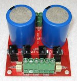
Or, if chassis mounting is impractical, discrete diodes chosen for low-Vfwd can operate just fine with small and inexpensive heatsinks on an ordinary PCB. The example below worked just fine, delivering a continuous 200 watts into an electronic load lab instruemt. Heatsinks are Aavid 577102B04000G (Digikey HS-368 $0.40 at qty=1)
_
Attachments
Last edited:
I am skeptical of the practicality..
Is this a fair comparison with a DIY PSU? I don't think that there are many people here that could achieve this level of sophistication in the garden shed. Have you seen the amount of SMD silicon in there...
It certainly is: now even for direct-to-mains supplies, the tendency is to go bridge-less (at least for server power supplies at the moment, but it will trickle down into all areas)Can this be an improvement?
https://www.google.com/url?sa=t&rct...?cl=en&usg=AFQjCNGlKGs81iSR0m3QDbH0jc_vvtvdhg
https://www.google.com/url?sa=t&rct...sg=AFQjCNGpiiPJwXvmwkscdZSW2OXoWunE_w&cad=rja
(Chapter 8)
Synchronous rectifiers are not inherently cleaner or noisier than their natural switchings counterparts: they are what the designer managed to achieve, but at least there is some control: with a traditional diode, you are stuck with its rev/rec behavior, but with a synchronous rectifier, you can achieve the best or the worst using the same components, it's just a question of control strategy.
Note that if you want to experiment, you don't need a specialized IC: it is relatively easy to come up with a simplistic discrete circuit doing the same.
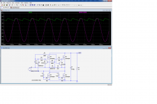
This example was designed to convert a 5VAC filament supply into a 6.3V DC one.
It is plain vanilla as shown, but since it is completely discrete, you can tweak it towards any target: cleanliness for example, if you add transition-control components
Attachments
Having read up some, I'm starting to think that this might have to be the way forward due to legislation. You can see that the chip has inputs from both mains and DC. This allows power factor correction to be applied and I think that this is becoming more important, especially on all kit > 75W. There's a lot of articles on the Linear website.
Switch mode PSUs really mess up the mains harmonics and the existing European transformer ban can only be expanded. How long before all non SMPS are banned including DIY?
Switch mode PSUs really mess up the mains harmonics and the existing European transformer ban can only be expanded. How long before all non SMPS are banned including DIY?
Is there a ban?the existing European transformer ban
All our power transmission from Power Station into our homes relies on transformers.
The ban's on small embedded stuff like the plug in wall transformers. You can't buy a standard transformer one now. They're all switchers. There's also legislation requiring some consumer goods to have automatic power save modes. It comes from the must read DIRECTIVE 2009/125/EC OF THE EUROPEAN PARLIAMENT AND OF THE COUNCIL of 21 October 2009 establishing a framework for the setting of ecodesign requirements for energy-related products. You'll be familiar with it from the bans on powerful vacuum cleaners and incandescent light bulbs  (I've stocked 1,000 60W bulbs in the garage so I'm okay )
I realise that we're not supposed to talk politics, but in this case the legislation might have a direct effect on your ability to build sound systems. And don't forget what the purpose of legislators is - to make more legislation. It's not inconceivable that all amplifiers will have to use active bridges to 'protect' the electrical system and thus the environment. Could they ban all domestic amplifiers > 100W RMS? What about an eco mode that automatically reduces output to 10W RMS after a period of 15 minutes? That would help preserve the acoustic environment. A burglar alarm now can't sound for more than 15 minutes otherwise you can be fined so it's not a ridiculous concept.
As the technology and legislation co develop, it's feasible that you'll see a merging of the four FETs and the controller chip into something ceramic that looks exactly like a current passive bridge but isn't.
(I've stocked 1,000 60W bulbs in the garage so I'm okay ) I realise that we're not supposed to talk politics, but in this case the legislation might have a direct effect on your ability to build sound systems. And don't forget what the purpose of legislators is - to make more legislation. It's not inconceivable that all amplifiers will have to use active bridges to 'protect' the electrical system and thus the environment. Could they ban all domestic amplifiers > 100W RMS? What about an eco mode that automatically reduces output to 10W RMS after a period of 15 minutes? That would help preserve the acoustic environment. A burglar alarm now can't sound for more than 15 minutes otherwise you can be fined so it's not a ridiculous concept.
As the technology and legislation co develop, it's feasible that you'll see a merging of the four FETs and the controller chip into something ceramic that looks exactly like a current passive bridge but isn't.
is that it?The ban's on small embedded stuff like the plug in wall transformers. You can't buy a standard transformer one now.
Just those tiny 1VA to 10VA plug ins?
High efficiency, low vampire power, and PFC. Not an explicit ban on 50Hz transformers, but a switcher handles all that and provides more output power for less cost, it's the natural route. Stock up on your old router wall warts.
And I appreciate having 100-240V inputs thanks to the APFC. But I fear the day class-AB amps get banned. Isn't tubes already being threatened?
I stand corrected, looking at the APFC sections of some PSUs.
Also I admit I missed out seeing that IC is meant for the secondary side. Good solution for a non-SMPS.
And I appreciate having 100-240V inputs thanks to the APFC. But I fear the day class-AB amps get banned. Isn't tubes already being threatened?
Synchronous rectifers are more use in high power supplies.
They are usually used in high amps SMPS where low forward voltage drop is important.
I stand corrected, looking at the APFC sections of some PSUs.
Also I admit I missed out seeing that IC is meant for the secondary side. Good solution for a non-SMPS.
Last edited:
Isn't tubes already being threatened?
What
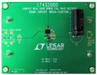
Do tell- I haven't read this...I ran across the LT4320 active bridge last night and found the example in data sheet particularly enlightening: that a 3A bridge can be made using tiny SMT quad MOSFETs and it doesn't heat up at all - no heatsink. Recently I have been building cap multipliers for Class A amps drawing upwards of 5A and notice that the square puck bridge rectifiers get plenty hot, even with a good heatsink. The loss of power, drop of voltage, and requirement for a large heatsink at these currents are problematic.
https://www.mouser.com/datasheet/2/609/4320fb-1271125.pdf
Look how small the controller and the 4 MOSFETs are:

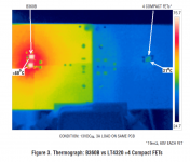
And here is the comparison vs regular diode bridge for same current:

The size is so compact, it could easily be snuck into the real-estate of typical Class A amp PCB and eliminate need for a heatsinked bridge.
https://www.mouser.com/datasheet/2/609/4320fb-1271125.pdf
Look how small the controller and the 4 MOSFETs are:
And here is the comparison vs regular diode bridge for same current:
The size is so compact, it could easily be snuck into the real-estate of typical Class A amp PCB and eliminate need for a heatsinked bridge.
Attachments
Last edited:
This tiny synchronous bridge is able to sustain 20A continuous and far over 100A in impulse, pulse duration ≤100 μs, duty cycle ≤1%.
It was designed to be drop in replacement for a standard diode bridge.
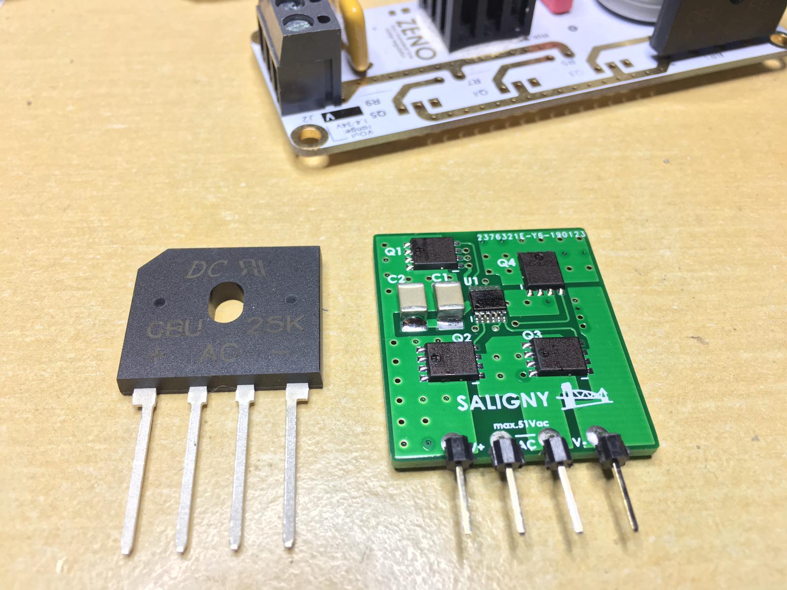
GB is here Ideal bridge rectifier GB
Regards,
Tibi
It was designed to be drop in replacement for a standard diode bridge.
GB is here Ideal bridge rectifier GB
Regards,
Tibi
Last edited by a moderator:
- Status
- This old topic is closed. If you want to reopen this topic, contact a moderator using the "Report Post" button.
- Home
- Amplifiers
- Power Supplies
- Active bridges - what next?