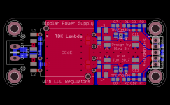
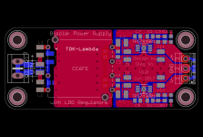
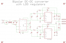
For comparison attached is the design without output sense but with more practical 3.5mm lead pitch output screw terminal and indicator LEDs for each rail. I guess when using the DC-DC converter it is safer to have short sense lines to avoid inducing the noise into the feedback circuitry.
Attachments
Last edited:
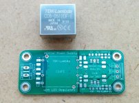
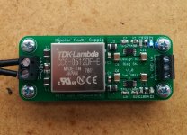
Assembled the PSU. Positive rail works but the negative rail did not come up. DC-DC converter output is OK for both rails but TPS7A3001 reg does not work. Replacing the reg did not help and since this is the only active element after the DC-DC converter I suspect bad regulator ICs. Both ICs, the one I soldered initially and the replacement are from the same batch. A couple of days earlier I assembled another project using the same ICs which worked but those ICs were bought roughly half a year ago. So I guess I'll look for an alternative source of the TPS7A3001 regs to finish the PSU.
Regards,
Oleg
Regards,
Oleg
Attachments
Thanks, JP!
I'll try to contact mouser and ask if there is known issue with recent batch of TPS7A30's.
I successfully soldered around 10 of such ICs (5 positive and 5 negative regs)
and did not fry or damage a single one until the recent batch of two I've got from
mouser which both failed.
I'll try to contact mouser and ask if there is known issue with recent batch of TPS7A30's.
I successfully soldered around 10 of such ICs (5 positive and 5 negative regs)
and did not fry or damage a single one until the recent batch of two I've got from
mouser which both failed.
Hi Jan,
The answer is yes and no. The design is new but it uses more or less copy/paste of the regulators part from the working design. I checked if there are manufacturing issues around the failed reg and did not find any. I really suspect the regs. I hope to check if it is really so in a couple of days after I get a new batch of regs from digikey.
The answer is yes and no. The design is new but it uses more or less copy/paste of the regulators part from the working design. I checked if there are manufacturing issues around the failed reg and did not find any. I really suspect the regs. I hope to check if it is really so in a couple of days after I get a new batch of regs from digikey.
Thanks Jan for making me look at the design again! One should never be too sure in his design skills")
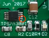
I found what the problem is. I looked at the PCB design in Eagle once again and found that there was no connection from the output pin of the TPS7A3001 (pin 1) to the output copper pour. I don't know how it happened but the gerbers I have submitted to the manufacturer had this error. So it is my fault in the end. I'll connect the output pin to the output copper pour by a solder blob and see if the reg turns on. I will probably order a new batch of PCBs with this error corrected.
I found what the problem is. I looked at the PCB design in Eagle once again and found that there was no connection from the output pin of the TPS7A3001 (pin 1) to the output copper pour. I don't know how it happened but the gerbers I have submitted to the manufacturer had this error. So it is my fault in the end. I'll connect the output pin to the output copper pour by a solder blob and see if the reg turns on. I will probably order a new batch of PCBs with this error corrected.
Thanks Jan for making me look at the design again! One should never be too sure in his design skills
I found what the problem is. I looked at the PCB design in Eagle once again and found that there was no connection from the output pin of the TPS7A3001 (pin 1) to the output copper pour. I don't know how it happened but the gerbers I have submitted to the manufacturer had this error. So it is my fault in the end. I'll connect the output pin to the output copper pour by a solder blob and see if the reg turns on. I will probably order a new batch of PCBs with this error corrected.
I believe this type of chip is 100% functionally checked at manufacturing, so it would be extremely unlikely that two would fail from the same purchase.
Was the feedback connection correctly connected to the output? How about the EN input? If the output is not connected but the feedback is, I would expect max output. If there is a valid EN.
Jan
Last edited:
The way it was is shown in the attached zoom-in. Notice missing connection from pin 1 to the output copper pour in the red circle. The feedback components R2, C10, R4 are connected as they should.
The EN pin is properly connected to VIN (upper left pin in the attached zoom-in) but I measure only -150mV on the output after I connected the output pin to the output copper pour.
The EN pin is properly connected to VIN (upper left pin in the attached zoom-in) but I measure only -150mV on the output after I connected the output pin to the output copper pour.
Attachments
Last edited:
- Status
- This old topic is closed. If you want to reopen this topic, contact a moderator using the "Report Post" button.
- Home
- Amplifiers
- Power Supplies
- DC-DC converter based PSU for line level applications