I use for 8-10 years a linear PSU at 12VDC / ~4AMPS home made.
I have built this PSU in order to replace the SMPS one of my LG video monitor which produced a lot of broad band RF noise, interfering a short wave radio receiver too much. I tried several ways to limit the noise with no acceptable results so I decided to avoid the SMPS PSU and built a linear one...
The PSU I built uses an LM338 TO-3 IC, in a typical layout, nothing fancy, a toroid transformer 230/16 VAC at ~7AMPS max, a bridge rectifier at 16AMPS, resistors, filter caps and protecting diodes to produce a stable and noiseless 12VDC output of supplying the LG monitor. The PSU is equipped with a temperature controlled fan to keep the IC cool.
Recently the PSU appeared a peculiar problem which makes the monitor to blink rhythmically occasionally.
I run some tests in order to realize what's going on and here are some results with no load and load:
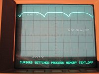
With no load: the DC output is 12.4VDC stable, a straight line as seen in scope.
With load: 230VAC input, 16.4VAC output on bridge terminals, ~3 AMPS AC current, 12.4 VDC at the output terminal.
The 12VDC output voltage as seen in the scope has on top a low frequency ripple as in the 1st pic.
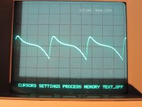
This AC voltage can be seen in the 2nd pic in higher resolution.
Any suggestion and help would be very appreciated.
I have built this PSU in order to replace the SMPS one of my LG video monitor which produced a lot of broad band RF noise, interfering a short wave radio receiver too much. I tried several ways to limit the noise with no acceptable results so I decided to avoid the SMPS PSU and built a linear one...
The PSU I built uses an LM338 TO-3 IC, in a typical layout, nothing fancy, a toroid transformer 230/16 VAC at ~7AMPS max, a bridge rectifier at 16AMPS, resistors, filter caps and protecting diodes to produce a stable and noiseless 12VDC output of supplying the LG monitor. The PSU is equipped with a temperature controlled fan to keep the IC cool.
Recently the PSU appeared a peculiar problem which makes the monitor to blink rhythmically occasionally.
I run some tests in order to realize what's going on and here are some results with no load and load:
With no load: the DC output is 12.4VDC stable, a straight line as seen in scope.
With load: 230VAC input, 16.4VAC output on bridge terminals, ~3 AMPS AC current, 12.4 VDC at the output terminal.
The 12VDC output voltage as seen in the scope has on top a low frequency ripple as in the 1st pic.
This AC voltage can be seen in the 2nd pic in higher resolution.
Any suggestion and help would be very appreciated.
Attachments
Last edited:
Could be the caps for sure.
You need to scope the input to the reg and make sure that the troughs in the ripple are not going below the stated dropout voltage of the reg which I think is around 3 volts for 5 amps output. So the input needs to be at 15 volts or higher (on the scope).
If it is, then the reg could be faulty. If not, the caps have deteriorated.
Thanks for the suggestions.
@ Nisbeth, Mooly & Osvaldo de Banfield: The filter caps are 2 x 4700uF in parallel, the ESR meter reads 8800uF / 0.00 ohms ESR, it seems that they are OK as well as the bridge rectifier.
I run some tests:
1. No load:
Input to "trafo" 223.00VAC, "trafo" secondary 16.20VAC, DC out on filter caps 21.10VDC, reg output 12.20VDC, reg adj pin 11.00VDC.
2. 2.16AMP DC load via a 50watt resistor:
"Trafo" secondary 15.40VAC, DC out on filter caps 17.40VDC, reg output 11.00VDC with ripple on top of the DC, reg adj pin 9.70VDC.
It seems to me that the reg cannot withstand the test load.
How can I check if the reg is faulty?
Last edited:
Usually regulators go open circuit or short out.
If you have two scope probes, you could test chan A-chan B to see if regulator is dropping the voltage, or the caps, or the transformer is too small for the load.
If load is pretty big you may need TO3 case regulator or a pass transistor on the TO220 regulator.
You can put 0.1 ohms between PS output and load to see how much current you are actually drawing. A-B test again I=V/R
You can test the transformer independently with load resistors, to see how much you can get out of it.
Last edited:
@ indianajo:
The voltage figures in my previous post may be present something.
But it is a TO-3 reg case as in my 1st post, the trafo is a bit an overkill one...TO3 case regulator
The voltage figures in my previous post may be present something.
If you have sufficient voltage drop across the reg, you can also check the version of cap multiplier, adjustable reg's can do it putting a cap between the adj pin and ground, and a couple of diodes to prevent reverse biasing during shut down. Search in the Texas, ST, Motorola or other IC manufacturer, you will easily found it.
How can I check if the reg is faulty?
Just scope the input to the reg. As long as the voltage is above 15.5 volts at all times (that's the dips in the ripple) then it would appear the reg is faulty. You have to scope it and look in real time.
@ Mooly, Yes you are right, the reg is faulty, it can drive only about ~1amp DC instead of ~5amps. I replaced it with a new one and now is OK.
The label on top of the faulty IC has faded out, may be it was a good fake IC since it lasted about 10 years...
Thanks for the suggestions everybody.
The label on top of the faulty IC has faded out, may be it was a good fake IC since it lasted about 10 years...
Thanks for the suggestions everybody.

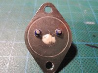
The faulty reg...
The curtain has finally fallen.
I was curious to see the inside view of the faulty reg, so I managed to open it up by using the force of a vice and with the aid of a screwdriver the top cover popped up...easily without any damage.
I'm not an expert to discern between a fake and a good one IC.
I believe that someone in the forum can do it.
Here's the pic attached.
Attachments
I wouldn't have thought it was an obvious part to fake tbh, and not going back a decade or so.
I'm not sure on the construction of those devices, but many TO3 packages used Beryllium oxide in their construction, I think for bonding the die to the can for good heat transfer and there can be a health risk if its cut (from the dust).
I'm not sure on the construction of those devices, but many TO3 packages used Beryllium oxide in their construction, I think for bonding the die to the can for good heat transfer and there can be a health risk if its cut (from the dust).
In principle, higher current regulators used a number of matched 317-like chips in parallel (or used to).The curtain has finally fallen.
I was curious to see the inside view of the faulty reg, so I managed to open it up by using the force of a vice and with the aid of a screwdriver the top cover popped up...easily without any damage.
I'm not an expert to discern between a fake and a good one IC.
I believe that someone in the forum can do it.
Here's the pic attached.
This example has only one chip, which seems suspicious (unless later versions had higher power chips)
- Status
- This old topic is closed. If you want to reopen this topic, contact a moderator using the "Report Post" button.
- Home
- Amplifiers
- Power Supplies
- Help, for problems in 12VDC Linear PSU.