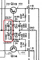
Circled in the pic attached. One is 220uf, the other 100uF. Not an error on the schematic as the installed parts are as shown. This is a Kenwood KA-8100. The regulator feeds the tone board and phono amp. Everything downstream from this regulator appears to be symmetrical, i.e. there is nothing being powered by only one side of the regulator.
Can anyone offer an explanation as to why Kenwood used non-matching caps here?
.
Can anyone offer an explanation as to why Kenwood used non-matching caps here?
.
Attachments
Last edited:
A few guesses:
1: An error from the designer that wasn't caught by production
2: There wasn't room for a 220u on the board for C35
3: The load on the negative supply needed a bit more filtering
Besides, it is the wrong place to put a capacitor as a zener has a low dynamic impedance. It doesn't do any harm, but it doesn't do much good either. A capacitor works best in high (relative) impedance environment.
Lars
..
4: They had a surplus of either and wanted to use them. Saves money.
most likely scenario....when you have an inventory of parts, will you just let them rot? or stuff them in?
It probably has to do with the power supply startup sequencing: I guess that initially they used identical caps, but noticed at some point undesirable effects, like circuit latch-up, power on thump, or something of the kind and found that delaying the -supply wrt.to the positive cured the problem
I am just looking for a reason....
...to make them both 220uF, or to keep them as designed. For me, Elvee's guess is enough of a reason to use original design values. Kenwood could have had made that choice intentionally...
Thanks guys. No need to bother with setting up an simulation.
...to make them both 220uF, or to keep them as designed. For me, Elvee's guess is enough of a reason to use original design values. Kenwood could have had made that choice intentionally...
Thanks guys. No need to bother with setting up an simulation.
Last edited:
I don't think there would be anything to report. I am just restoring this unit. Thought maybe I stumbled upon a mistake. But I will use orig design values, so there shouldn't be any problems. EDIT: Those are really hard to get to. And I am not as much into experimenting as I am fixing things. Different points of view I guess.
BTW, in this regulator those 25v caps have 25v on them. The larger 330uF 35v caps have 39v. So I will definitely up the voltage ratings on new caps to 35v and 50v respectively. To me, under-rating the voltage on those caps does seem like a mistake on Kenwood's part. Yes or no?
BTW, in this regulator those 25v caps have 25v on them. The larger 330uF 35v caps have 39v. So I will definitely up the voltage ratings on new caps to 35v and 50v respectively. To me, under-rating the voltage on those caps does seem like a mistake on Kenwood's part. Yes or no?
Last edited:
upgrading to 35 and 50 volt caps is a step in the right direction.....
depends, what year was that unit manufactured,
what were the mains voltage designations then?
and what is the actual mains voltage now?
knowing all this we can say for sure....
when i build my amps, i do not run caps on the brink,
i strive for 80% of cap rating or close to it, another consideration
is how high will your line voltage be and
how high will the voltage across the caps rise?
a simple fix would be series resistors on the secondary ac line
feed to the psu rectifiers...
To me that does seem like a mistake on Kenwood's part. Yes or no?
depends, what year was that unit manufactured,
what were the mains voltage designations then?
and what is the actual mains voltage now?
knowing all this we can say for sure....
when i build my amps, i do not run caps on the brink,
i strive for 80% of cap rating or close to it, another consideration
is how high will your line voltage be and
how high will the voltage across the caps rise?
a simple fix would be series resistors on the secondary ac line
feed to the psu rectifiers...
hmmm...never had that issue before.....but then i was more into tubes now....
I'm guessing the amp hasn't a speaker delay relay... perhaps the op could confirm that.
Altering the speed rails rise and decay isn't generally a good fix from an engineering point of view, its more of a fiddle but if it works and all that

Ideally all equipment should be silent at power on and power off however adding relays and the appropriate circuitry adds to the overall costs.
The 2nd pair would be at 25v regardless. On the back of the amp it says rated for 120v, and my actual mains are 120.5v. So the first pair is running over their rating while the house AC is almost dead-on.
I have seen this in other amps. Maybe cap ratings were considered to be conservative back then (1978) such that running at max voltage was normal? I don't know, you guys are the experts, lol. You tell me.
I have seen this in other amps. Maybe cap ratings were considered to be conservative back then (1978) such that running at max voltage was normal? I don't know, you guys are the experts, lol. You tell me.
1978
enough for me to go on a recapping spree...
can you post the actual kenwood model?
- Status
- This old topic is closed. If you want to reopen this topic, contact a moderator using the "Report Post" button.
- Home
- Amplifiers
- Power Supplies
- Is there a reason why the output caps in this regulator don't match?