Nirvana is more like Dantes Inferno ..
Everything that could go wrong..did. Then we made some mistakes like using 2 PI filters in series (with the first one having less attenuation)
Then feedback network started oscillating ..
Last update today...output after the PI filter (using only one PI filter and especially using a very small inductor of 1.2uH) is 2.5mV
I think that the road to Nirvana is , by definition , complicated but worth it.
Now the Active noise filter is creating problems..we are making new unit.
Thats where we stand. We can see the light...but we are not of the woods yet.
Last thing...I never seen such waveform on oscilloscope on any SMPS..ever .Looks like a LPS ( extremely clean at 1Mhz bandwidth, testing at 20Mhz will be done soon)
A setback but it appears that you are making progress. Is the difficulty related to getting the 3A output? and would it be easier to configure for 1-2A that would be sufficient to power the Katana stack. The Pi is most likely to be powered separately in most cases, and a cheap SMPS would suffice for that.
While we're at it, you might also try to hook up a quality supply to your router.")
indeed. Or rather, LOL! Please, If you want to advocate that a router make any difference, supply real documentation of this...
I think you spred "snake oil" ideas in the "computer audio" field :-(
//
Last edited:
A setback but it appears that you are making progress. Is the difficulty related to getting the 3A output? and would it be easier to configure for 1-2A that would be sufficient to power the Katana stack. The Pi is most likely to be powered separately in most cases, and a cheap SMPS would suffice for that.
Our goal is 3A not 2 or 2.5A
Problems are not related to output power they are related to complex interactions between PI filter , feedback loop and active cancellation (using a 200Mhz Opamp )
The PI with its rather mediocre (powerrail) architecture better gets a stable and clean supply for best performance.
Don't underestimate that!
While we're at it, you might also try to hook up a quality supply to your router.
Enjoy.
So true. I naively thought I could use a cheap PSU for my Pi and and reserve the good juice for the DAC. Nope...SQ took a major hit. You are far better off sharing one good PSU between the DAC and Pi via Kali than you are putting a separate, cheap supply on the Pi. Of course, two separate high quality supplies kick it up to the next level.
I think you spred "snake oil" ideas in the "computer audio" field
Yep, that's what I'm doing since more then 10 years... ...at least that's what ignorant people like you like to point out all the time.
Many of the issues we - the snakeoil fraction - brought up over time are today part of products and product lines. That's a fact!
The real problem: With people like you around, we'd still be living in caves.
And. I consider myself somebody who offers everybody through community contributions to have a closer look at the subjects I'm bringing up. My aim is not just to spread hot-air insults or rumors.
****
While we're at it. People shouldn't neglect the server (HW and SW) and network cables either. We're looking at an "organism" where everything matters. Unless there's a DAC which is able to cope with "all" upstream originated flaws, you'll face issues. If the "magnitude" of issues matters to you, is a different issue. Trying to solve this and that issue upstream is IMO well worth the effort... ...even if those noisy wannabe experts will tell you otherwise.
Enjoy.
Last edited:
Finally the "complex interaction" ...was in fact EMI picked up by probes (differential probes )
1Mhz bandwidth..the ground noise (default) on oscilloscope its observed at 625uV
Attached is what we can read on Nirvana output at 1Mhz with a 1A load. (after active filter) at cables connector (pcb)
Noise and ripple of 721uV (150uV over ground noise)
Even better , at 20Mhz noise we observe the same (about 800 uV instead of 721) but we see some HF spikes of 6mV that are also observed in the ground of oscillator at about 3mV).
Still some issues remain..3A we see a drop of 350mV (too high) and testing on each load has to be completed. Of course more testing on the HF spike seen..
While testing all those issues , final PCB will be designed starting Monday .Box also needs to be designed.
Again. There is NO SMPS on the market coming even close to Nirvana. Test data is very clear .
Best 5V SMPS by any company , ever.
Attachments
JP , I dont think you have LPS that can go lower than 50uV peak/peak 1Mhz bandwidth unless they use a LDO. Nirvana has no LDOs .
Second , across the 0-20Khz we are measuring less than 1.5uV on AP but of course in my books thats meaningless since any DAC/device have LDOs that are great in 0-500Khz (even in Mhz for some devices)
At last , we will start earthing/casing ground next week
Second , across the 0-20Khz we are measuring less than 1.5uV on AP but of course in my books thats meaningless since any DAC/device have LDOs that are great in 0-500Khz (even in Mhz for some devices)
At last , we will start earthing/casing ground next week
JP , I dont think you have LPS that can go lower than 50uV peak/peak 1Mhz bandwidth unless they use a LDO. Nirvana has no LDOs .
Second , across the 0-20Khz we are measuring less than 1.5uV on AP but of course in my books thats meaningless since any DAC/device have LDOs that are great in 0-500Khz (even in Mhz for some devices)
At last , we will start earthing/casing ground next week
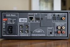
Any conclusions from the earth/ground tests? My guess is that any effect will be system-equipment chain dependent so a switchable 'float/ground' option may be best. Noted this option in the new streamer from Naim...
Attachments
Yeap thats exactly what we will have (sw floating / ground)
This week we concentrated on common mode noise (differential noise stays at at about 300uV pk/pk at 1Mhz bandwith) and in our tests we have decrease from 150mV (tested with unbalanced probes 20Mhz/2A) to 9mV. We are concluding the CMN tests in the next few days. We found the alu box and every change will be incorporated in the new PCB (new pcb stays 99% same but we are adding 0.8cm to each side so we can slide it in alu casing.
We have also tested IFI, Nokia and some OEM brands SMPS and the minimum we have seen (with unbalanced probes at 20Mhz/2A) is 86mV.. (and yes that was the IFI)
Bridge rectifier snubbing (RC)
We have found that a lot of EMI on the oputput comes from bridge rectifier diodes. Simply changing the RC snubber makes a lot of difference on the output (emi almost doubles on the output without RC snubber)
We are fine tuning the values of R (first) and C for the best EMI on the output.
This is the last element that we are "taming"
We are fine tuning the values of R (first) and C for the best EMI on the output.
Soft recovery is probably more important than fast turn-off for rectifier diodes to help control or eliminate inductor or transformer ringing, but some combination of both is good. Schottky diodes are fast but not as soft as some, in some cases they can add more noise problems. Some soft recovery types here: soft recovery Discrete Semiconductors | Mouser
I was very dubious about soft recovery diodes. I said to myself they can only be like perhaps an RC snubber to each diode. Well, I never equaled a soft recovery diode with an RC snubber. My feeling is it is just an internal capacitance, however it's perfectly placed. It's worth saying these things are not easy to measure, It's said an RC snubber makes a single event spike into a series of lower frequency ripples. That seems likely. Also either-net over mains is more easy to measure.
Douglas Self says says we are likely to get better results with a VAS transistor if the collector to base capacitance is very low and an external high grade capacitor is fitted. Various reasons about linearity given. Others say older amplifier designs were more stable due to the high capacitance of the VAS devices ( and many other reasons ). The soft recovery diode suggests it's not quite that simple. Doubtless to call it capacitance is too simplistic. It's the how and the why it is there. FET's tend to work well as rectifiers as they work differently. Alas too little is written on this.
Active rectification - Wikipedia
mosfet - Why does this Bridge Rectifier claim to have no [Diode] Forward Voltage drop - Electrical Engineering Stack Exchange
- Status
- This old topic is closed. If you want to reopen this topic, contact a moderator using the "Report Post" button.
- Home
- Amplifiers
- Power Supplies
- Best 5V SMPS ?