This will be a test bench report of Connexelectronics SMPS240QR, +/- 30V version. I won't copypaste the specs from the PDF linked above, only the important matters.
Input : 230VAC
Outputs : +/- 30V and +12V
Topology : quasi-resonant, rated for 240W output on the +/-30 rails.
On-board Mains filter.
Unregulated output. This means the output follows the voltage on the mains input cap.
No Power Factor Correction.
Reasonable price (€55).
Initial impressions :
Positive :
- Small, compact, light.
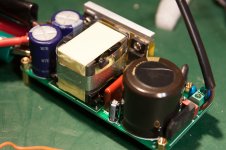
- The supply seems well built, PCB is a real double sided FR4 PCB
- There is a temperature sensor glued to the switching transistors
- Caps are 105°C... all in all, it looks good.
Negative :
- Schematics are unavailable.
- Layout is a bit tight around the output connector and requires nimble fingers
- Resonant capacitor looks a bit small.
Necessary parts not included in the package :
- Insulating sheet to be placed under the board, if mounted on a metal plate. I used photocopier-safe transparency film, which is quite thick and resists high temperatures.
- Silpads to be placed between the bottom-side secondary diodes and the metal enclosure.
Tests under load
Well, it works and it is within spec*, so no problem here. Considering it is unregulated, it could be interesting to invert one of the amp channels to spread the load between both polarities.
* = Ripple would be out of spec if this was the 32V version, but this is the 30V version, which qualifies as "custom" and has relaxed ripple requirements... okay, this might be cheating a little bit...
Attached files :
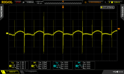
- ripple with 2A load on V+, V-, and both.
- ripple with 3.7A load on both outputs.
Next : EMI/RFI/Noise
Input : 230VAC
Outputs : +/- 30V and +12V
Topology : quasi-resonant, rated for 240W output on the +/-30 rails.
On-board Mains filter.
Unregulated output. This means the output follows the voltage on the mains input cap.
No Power Factor Correction.
Reasonable price (€55).
Initial impressions :
Positive :
- Small, compact, light.
- The supply seems well built, PCB is a real double sided FR4 PCB
- There is a temperature sensor glued to the switching transistors
- Caps are 105°C... all in all, it looks good.
Negative :
- Schematics are unavailable.
- Layout is a bit tight around the output connector and requires nimble fingers
- Resonant capacitor looks a bit small.
Necessary parts not included in the package :
- Insulating sheet to be placed under the board, if mounted on a metal plate. I used photocopier-safe transparency film, which is quite thick and resists high temperatures.
- Silpads to be placed between the bottom-side secondary diodes and the metal enclosure.
Tests under load
Code:
I(V+)   V+ (V)      Ripple  I(V-)   V- (V)     Ripple
(Amps)  (Volts)     (Vpp)   (Amps)  (Volts)    (Vpp)
0       +32.3       --      0       -32.4       --
0       +31.7       --      2       -30.7       0.640
2       +30.6       0.680   0       -33.6       --
2       +29.9       0.980   2       -29.9       0.940
3.7     +28         2.2     3.7     -28         2.2
Well, it works and it is within spec*, so no problem here. Considering it is unregulated, it could be interesting to invert one of the amp channels to spread the load between both polarities.
* = Ripple would be out of spec if this was the 32V version, but this is the 30V version, which qualifies as "custom" and has relaxed ripple requirements... okay, this might be cheating a little bit...
Attached files :
- ripple with 2A load on V+, V-, and both.
- ripple with 3.7A load on both outputs.
Next : EMI/RFI/Noise
Attachments
Last edited:
I added 3.7A load, which is the best I can do with these huge power resistors. I could add the extra resistors to reach 4 amps, but that would require locating some more power resistors... and I'm not really motivated.
If you guys know what the display usually looks like on Rigol DS2000 scopes, you're probably wondering why I have hires/time averaging mode turned on. Well, there was a bit of a snag about the noise...
Part 2 : EMI/RFI
Measuring the output voltage using the traditional 6" scope probe ground alligator clip wire is a futile effort, as is usually the case when in the vicinity of a SMPS. I will not post the scope shots, because these measurements are all fake, since the ground alligator clip wire behaves as a nice loop antenna of unspecified characteristics.
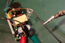
Now, what would happen to, say, an audiophile circuit located a few inches away from this power supply? Some magnetic coupling will occur, so I will explore around the supply using a simple loop antenna, loaded with 50R and fed into the scope with a coax. Flattening the loop discriminates between capacitive and inductive coupling. If the squeezed flat loop still picks it up, it's capacitive. If only the nice round loop picks it up, it's inductive.
So far, the transformer seems to leak quite a bit of magnetic field. As expected, worst spots are above and below, then to the sides (along the length of the board).
The front and back of the board (where the connectors are located) are much quieter.
Scope shot : voltage from aforementioned loop antenna, placed as shown on photograph.
If you guys know what the display usually looks like on Rigol DS2000 scopes, you're probably wondering why I have hires/time averaging mode turned on. Well, there was a bit of a snag about the noise...
Part 2 : EMI/RFI
Measuring the output voltage using the traditional 6" scope probe ground alligator clip wire is a futile effort, as is usually the case when in the vicinity of a SMPS. I will not post the scope shots, because these measurements are all fake, since the ground alligator clip wire behaves as a nice loop antenna of unspecified characteristics.
Now, what would happen to, say, an audiophile circuit located a few inches away from this power supply? Some magnetic coupling will occur, so I will explore around the supply using a simple loop antenna, loaded with 50R and fed into the scope with a coax. Flattening the loop discriminates between capacitive and inductive coupling. If the squeezed flat loop still picks it up, it's capacitive. If only the nice round loop picks it up, it's inductive.
So far, the transformer seems to leak quite a bit of magnetic field. As expected, worst spots are above and below, then to the sides (along the length of the board).
The front and back of the board (where the connectors are located) are much quieter.
Scope shot : voltage from aforementioned loop antenna, placed as shown on photograph.
Attachments
Last edited:
It's a pity that the output scales with mains (no universal mains input), because that's one of the main motivations to use SMPS for me, besides form factor, efficiency etc.
Also, the single +12V/0.3A Aux ouput is a bit awkward for a front end supply in an amp or active speaker etc.
Still a nice product, and thanks for the test.
Also, the single +12V/0.3A Aux ouput is a bit awkward for a front end supply in an amp or active speaker etc.
Still a nice product, and thanks for the test.
@peufeu
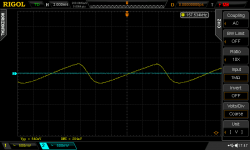
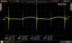
On my FSFR2100SX LLC converter output ripple looks like this (no averaging, only BW limited channel, same DS2000 scope):

It is noticeable almost pure sinusoidal ripple and very small glitches produced in dead-time period of switching sequence.
On my FSFR2100SX LLC converter output ripple looks like this (no averaging, only BW limited channel, same DS2000 scope):
It is noticeable almost pure sinusoidal ripple and very small glitches produced in dead-time period of switching sequence.
Attachments
It would be better if it was regulated, yeah...
But resonant and quasi-resonant supplies don't have enough range for a universal input (100-240V) anyway. An active boost PFC would be needed to achieve this, adding to cost.
yu3ma : Your output is very clean. How is your measurement setup? (cables, load, etc?)
Cheap EMI tweak #1 : copper tape
I decided to simulate the layout I had in mind for my amplifier enclosure, which is the usual model with heat sinks on the side. I would have paced the supply in the middle, mains side facing the back panel, and one amp board on each heatsink, on both sides of the supply.
So, I set the loop antenna's edge 5cm away from the edge of the supply PCB, and measured induced noise, which was about 2.8 mV RMS into 50R.
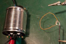
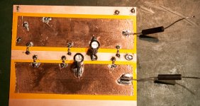
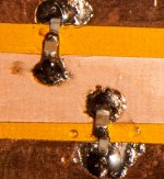
I then added a copper band around the transformer (see photo), to create a shorted turn around the whole transformer (not around the secondary!). This reduces flux leakage, as shown by before/after scope shots.
Noise is reduced about 18dB by this very simple tweak! Why the manufacturer did not include this is beyond me.
I should probably connect the copper tape to Earth or primary side GND to reduce capacitive coupling between transformer windings, though.
But resonant and quasi-resonant supplies don't have enough range for a universal input (100-240V) anyway. An active boost PFC would be needed to achieve this, adding to cost.
yu3ma : Your output is very clean. How is your measurement setup? (cables, load, etc?)
Cheap EMI tweak #1 : copper tape
I decided to simulate the layout I had in mind for my amplifier enclosure, which is the usual model with heat sinks on the side. I would have paced the supply in the middle, mains side facing the back panel, and one amp board on each heatsink, on both sides of the supply.
So, I set the loop antenna's edge 5cm away from the edge of the supply PCB, and measured induced noise, which was about 2.8 mV RMS into 50R.
I then added a copper band around the transformer (see photo), to create a shorted turn around the whole transformer (not around the secondary!). This reduces flux leakage, as shown by before/after scope shots.
Noise is reduced about 18dB by this very simple tweak! Why the manufacturer did not include this is beyond me.
I should probably connect the copper tape to Earth or primary side GND to reduce capacitive coupling between transformer windings, though.
Attachments
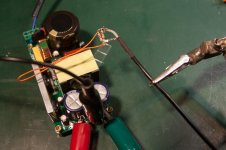
EMI tweak #2: Canned vegetables
The picture explains it all (along with showing the position of the measurement loop).
The copper tape is still there. I had enough trouble sticking it in to NOT want to tear it out just to have more dynamic range for the shield measurement. Therefore, the amount of noise to be measured is quite small, and scope noise becomes a major factor.
Besides, we're interested in the sawtooth signal (which is inductively coupled), not by the switching spikes (which are coupled by some other means), and these spikes represent a non-negligible proportion of the measured signal. Therefors, the scope's displayed RMS values should not be used.
So, I will instead eyeball the sawtooth signal and say the shield brings something like a 10-20dB improvement. Which, again, isn't that bad for a €0.50 can of cooked vegetables.
Advice for Connexelectronics: Make a sheet metal shield enclosure for a cost of $0.5 ; sell it along with the PSU for $5. No problem here.
Anyway. With the shield, I'm gonna say the noise is low enough to stick it inside the amp's enclosure, but I'll rotate it 90° and mount it as close as possible to the front panel, to keep it away from the inputs etc, which are of course on the back panel.
Attachments
It may get too hot from eddy currents, notably with an air-gap type of xformer design, that's what I've been told from a SMPS designer.Why the manufacturer did not include this is beyond me.
yu3ma : Your output is very clean. How is your measurement setup? (cables, load, etc?)
@peufeu
I use only those metal spring on top of probe for GND connection, nothing special.
Probe is placed directly on output connector.
For load, I use standard wire-wound resistors but I done frequency compensation on them, added R/C to compensate inductive component so I get almost non-inductive load from those resistors - very useful for transient testing.
Okay, so no long ground alligator wire! Still, your output is really clean.
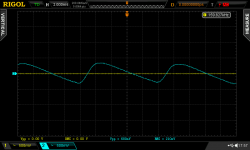
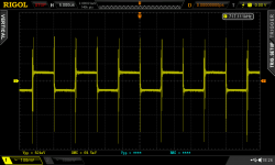
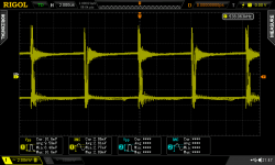
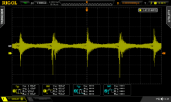
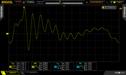
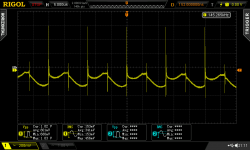
My turn now: output ripple, without any filtering. Load is still 2A. This is measured by soldering a coax to the output. Shield on GND and center on V+, with a 50R resistor of course. Coax has a clamp-on ferrite core.
Huge HF noise spikes are not that hard to spot here, eh?
Well, there is no filtering on the output. The diodes feed a pair of large caps... but there are no ceramic caps in parallel, nothing at all.
So, the datasheet ripple spec of 150mVpp at 100kHz seems bollox, it's closer to 250-300 mVpp if you squint hard enough to not look at the huge HF spikes, which the scope registers at 3Vpp.........
Ahem.
Attachments
Damn, I'm gonna have to build your power supply then! That could be interesting...
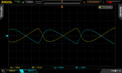
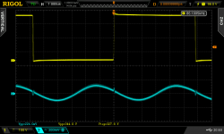
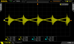
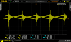
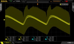
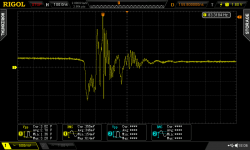
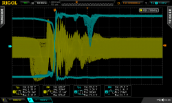
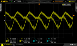
Yet another shot.
Transformer Secondary voltage (blue)
Output voltage (yellow)
I doubt that a snubber across the secondary, or on the output diodes, could do anything from that ringing. It doesn't look like diode ringing, rather it seems to come from the primary side.
Yet another shot.
Transformer Secondary voltage (blue)
Output voltage (yellow)
I doubt that a snubber across the secondary, or on the output diodes, could do anything from that ringing. It doesn't look like diode ringing, rather it seems to come from the primary side.
Attachments
Damn, I'm gonna have to build your power supply then! That could be interesting...
Yet another shot.
Transformer Secondary voltage (blue)
Output voltage (yellow)
I doubt that a snubber across the secondary, or on the output diodes, could do anything from that ringing. It doesn't look like diode ringing, rather it seems to come from the primary side.
looks like a flyback converter? Is so, there is not much you could do about that.
Damn, I'm gonna have to build your power supply then! That could be interesting...
At least try, I will provide help as much as I can.
LLC topology in general is very interesting, take a short break and watch this nice introduction video:
https://youtu.be/ssL5scfIFZ8
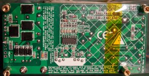
Okay, here is the back side of the board as requested.
The output capacitor is 3300µF, ESR=35mOhm, ESL=14nH so not very good at filtering HF noise.
I added capacitors in parallel at the output :
- 47µF 63V EEUFR (4nH, ESR 70 mOhms measured)
- 1 µF 50V X7R 0805 (with 0R1 0603 resistor in series)
Output noise spikes are lower in level, but these aren't the kind of spikes you get rid of with just a simple cap. A LC filter with a lossy ferrite bead is required, however I don't have beads rated for this DC current at hand.
And no amount of LC filtering on the output can get rid of the common mode noise from switching...
Enough for today. I'm a bit disappointed by this supply...
Attachments
Very interesting video, yu3ma!
When I purchased this power supply, the intent was to make my life simple, stick it in an enclosure and call it a day, and finish my Modulus-86 kit which has been waiting for a year! (sorry Tom)
You know, it's marketed as "low-noise" "next-generation quasiresonant" etc...........
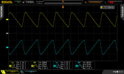
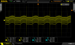
I located a few suitable ferrites. And although constructing DIY planar capacitors is definitely interesting, it isn't really a timesaver...
- 47µF Panasonic FR cap (ESR 70 mOmh)
- 3x 1µF X7R 50V in series with 0R1 0603 (chip resistors mounted upside down of course! half the ESL...)
- and copper tape and kapton
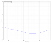
Result has ESL of 180pH and 33-70mOhms ESR (according to network analyzer, impedance graph attached).
Sharp HF spikes are exterminated (from 3Vpp before tweaking to invisible on the scope) and only a 70mVpp ripple remains at the switching frequency. A bit of ringing at a few MHz is now visible (it was previously obscured)...
Conclusion/product evaluation: Meh.
When I purchased this power supply, the intent was to make my life simple, stick it in an enclosure and call it a day, and finish my Modulus-86 kit which has been waiting for a year! (sorry Tom)
You know, it's marketed as "low-noise" "next-generation quasiresonant" etc...........
I located a few suitable ferrites. And although constructing DIY planar capacitors is definitely interesting, it isn't really a timesaver...
- 47µF Panasonic FR cap (ESR 70 mOmh)
- 3x 1µF X7R 50V in series with 0R1 0603 (chip resistors mounted upside down of course! half the ESL...)
- and copper tape and kapton
Result has ESL of 180pH and 33-70mOhms ESR (according to network analyzer, impedance graph attached).
Sharp HF spikes are exterminated (from 3Vpp before tweaking to invisible on the scope) and only a 70mVpp ripple remains at the switching frequency. A bit of ringing at a few MHz is now visible (it was previously obscured)...
Conclusion/product evaluation: Meh.
Attachments
Last edited:
- Status
- This old topic is closed. If you want to reopen this topic, contact a moderator using the "Report Post" button.
- Home
- Amplifiers
- Power Supplies
- Test Bench : SMPS240QR from Connexelectronics