I need some help. The mentioned SMPS is in not working condition.
Amazing is the fact, that after switch off the SMPS works for a second (i. e. all voltages are present for a short moment), both in connected condition and not connected condition with the mixer-mainboard.
Replacing of electrolytic caps don't provide any success and I observe the same behaviour.
What can I do additional for perform the troubleshooting and fix the failure ?
I have heard from various service shops, that most other devices from this SMPS model suffers under this issue - go to
http://linux-audio.4202.n7.nabble.c...SU2-for-an-Eurorack-UB2442FX-PRO-td42515.html
This means for me, that the reason for not operating condition must be good known. Maybe one of the members know exact the parts, which I must replace.
Thanks for your help.
schematic is here:
https://bmamps.com/Schematics/Behringer/UB2442_UB-SPSU2 REV D.pdf
TOP245Y datasheet and advices from the manufacturer are here:
TOP245Y Datasheet(PDF) - Power Integrations, Inc.
https://www.power.com/search/site/top245y/
Datasheet of the used fast recovery rectifier diodes is here (50ns Diode HER300 oder HER303)
http://datasheet.octopart.com/HER302-T-Diodes-Inc.-datasheet-65451.pdf
The german URL under
http://www.mikrocontroller.net/topic/273431
don't provide any advice.
Last edited:
Thank you for your fiirst advices.
In the schematic of the application examples from datasheet there are good known types (1N4148 UF4001-4007, UF5402 and BYV32). Are this versions a better choice than the currently used ?
I have also read on some platforms, that D3 is known to fail, but this must actually have a very specific reason. Either the design isn't correct or the used type isn't the appropriate choice.
Against the idea with a defective diode is the fact, that after turning off the main voltages the secundary voltages shortly present in the correct values.
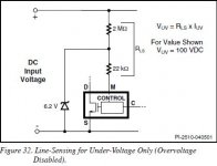
This was my first idea. But the TOP245Y haven't the mulfifunction PIN "M". Instead this there is a PIN "L". Maybe the 2 meg-ohms resistor (3 times 680K chip resistors in serial configuration) is in faulty condition while operation (static measuring with ohm meter provides the correct value of 2 meg-ohm)Looks like the Top is reacting on an overvoltage (right or wrong?)
You could try diabeling the sensing.If it helps then replace the IC (or not).
Mona
already done without success. Maybe the diode is faulty only while operating and not while checking by a diode testercheck capacity of C13, or replace without checking, and check the diode feeding C13
Also all this diodes mayby in faulty condition only while operating and not while checking by a diode tester. This means, all diodes I have to replace on suspicion. But which types provides a maximum of realibility (the genuine types from the schematic I don't find and don't know (4x303, 1x207, 1x10⁴ and 1x 10⁷ - maybe HER series from "DIODES").D3 is known to fail, when it does the TOP goes into protect mode. Also check the secondary diodes, if they fail, it will also just pump and stop repeatedly.
In the schematic of the application examples from datasheet there are good known types (1N4148 UF4001-4007, UF5402 and BYV32). Are this versions a better choice than the currently used ?
I have also read on some platforms, that D3 is known to fail, but this must actually have a very specific reason. Either the design isn't correct or the used type isn't the appropriate choice.
Against the idea with a defective diode is the fact, that after turning off the main voltages the secundary voltages shortly present in the correct values.
Last edited:
It is the "L" pin for over-voltage sensing.They made some of a mess of it in the datasheet.Thank you for your fiirst advices.
This was my first idea. But the TOP245Y haven't the mulfifunction PIN "M". Instead this there is a PIN "L". Maybe the 2 meg-ohms resistor (3 times 680K chip resistors in serial configuration) is in faulty condition while operation (static measuring with ohm meter provides the correct value of 2 meg-ohm)
Mona
Attachments
Thank you for this advice - fig 17 provides the right advice. The SMPS works now correct, but a new question rises up.It is the "L" pin for over-voltage sensing.They made some of a mess of it in the datasheet.
Mona
On the datasheet (page 11) there is to read the follow:
LINE-SENSE (L) Pin Operation (Y and R Packages)
When current is fed into the LINE-SENSE pin, it works as a voltage source of approximately 2.6 V up to a maximum current of +400 μA (typical).
At +400 μA, this pin turns into a constant current sink. Refer to Figure 12a. In addition, a comparator with a threshold of 1 V is connected at the pin and is used to detect when the pin is shorted to the SOURCE pin.
There are a total of four functions available through the use of the LINE-SENSE pin: OV, UV, line feed forward with DCMAX reduction, and remote ON/OFF. Connecting the LINE-SENSE pin to the SOURCE pin disables all four functions.
The LINESENSE pin is typically used for line sensing by connecting a resistor from this pin to the rectified DC high voltage bus to implement OV, UV and DCMAX reduction with line voltage.
In this mode, the value of the resistor determines the line OV/UV thresholds, and the DCMAX is reduced linearly with rectified DC high voltage starting from just above the UV threshold.
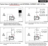
The pin can also be used as a remote on/off and a synchronization input. Refer to Table 2 for possible combinations of the functions with example circuits shown in Figure 16 through Figure 40.
A description of specific functions in terms of the LINE-SENSE pin I/V characteristic is shown in Figure 11 (right hand side). The horizontal axis represents LINE-SENSE pin current with positive polarity indicating currents flowing into the pin. The meaning of the vertical axes varies with functions. For those that control the on/off states of the output such as UV, OV and remote ON/OFF, the vertical axis represents the enable/disable states of the output. UV triggers at IUV (+50 μA typical with
30 μA hysteresis) and OV triggers at IOV (+225 μA typical with 8 μA hysteresis).
Between the UV and OV thresholds, the output is enabled.
For line feed forward with DCMAX reduction, the vertical axis represents the magnitude of the DCMAX. Line feed forward with DCMAX reduction lowers maximum duty cycle from 78% at IL(DC) (+60 μA typical) to 38% at IOV (+225 μA).
With the 2 meg-ohms resistor from fig. 17 (previous post resp. page 16 from datasheet) the UV and OV thresholds at my faulty power supply device are between 80 and 170VDC (checked with isolation transformer with adjustable voltage) instead the mentioned 100 and 450VDC in the datasheet.
With a used usual available step-down transformer from 230VAC to 110VAC the SMPS works correct. Next step was the enhance of the 2MΩ resistor to 4,8MΩ at whole (serial network consist from 2x680K and 1MΩ and 2,2MΩ) and operating again with the in Germany typicall value for the mains input voltage from 230VAC. Even in this configuration the SMPS works correct.
Actually one can rule out, that defective diodes or electrolytic caps causes this behaviour.
What could be the reason therefore (the 2MΩ resistor was in the genuine condition realize by a serial network consist of 3x 680K chip resistor - but all resistors are not defectice) ?
Maybe the conversion from voltage source character to a constant current sink character takes place at a lower current value ? In this case the TOP245Y itself must be replace.
Thank you very much for advices.
Last edited:
I also have a problem with my power supply, my model is SPSU1 from a Xenyx 1222FX and not SPSU2 but it looks almost the same.
It started working wierd until it did not show any lights when powering up, I´ve opened up and replaced some bulged capacitors last year. Tested and worked great. Now I started having problems again but I had output voltages but not very stable and this time I replaced all the capacitors including those little ones, on the hot side that had a little high ESR. After replacing all capacitors now I don't have +15v and I ear a clicking sound from the power supply which I don't know what´s causing it.
It started working wierd until it did not show any lights when powering up, I´ve opened up and replaced some bulged capacitors last year. Tested and worked great. Now I started having problems again but I had output voltages but not very stable and this time I replaced all the capacitors including those little ones, on the hot side that had a little high ESR. After replacing all capacitors now I don't have +15v and I ear a clicking sound from the power supply which I don't know what´s causing it.
Just found my problem. The problem was that I lost a round plastic piece that isolates the screw of bd239 from ground. Tried without the screen and the power supply works fine with the correct voltages. Now I just need go get a replacement for that round plastic piece to put the screw in again.
All capacitors of my power supply were replaced, except the big one as well as those SMD.
Finally the mixer is alive
All capacitors of my power supply were replaced, except the big one as well as those SMD.
Finally the mixer is alive
- Status
- This old topic is closed. If you want to reopen this topic, contact a moderator using the "Report Post" button.
- Home
- Amplifiers
- Power Supplies
- Behringer SMPS Model UB-SPSU2 with TOP245Y (used in Mixer Model UB1204) death