Hello!
I'm a newcomer to this so please bear with me.
The IRFP240/9240 that the capmx board calls for are showing up as obsolete or out of stock at the usual sources - as are their recommended Fairchild replacements. From what I'm reading, this isn't a new issue.
I'm sourcing parts and wondering if there are any preferred replacements that are more recent?
Thanks.
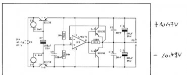
Hello Ground point . I have used 9140 and 250 for my build and just this afternoon have given it a low voltage test.
So here I ask advice also!
My negative rail is 1v more than the positive. I thought both of these transistors gave a 4v drop?
How would I best tweak this please. I tested with 13.8vac and I ended up with 13.8(!) Positve and 14.8v negative.
Thanks in advance
So here I ask advice also!
My negative rail is 1v more than the positive. I thought both of these transistors gave a 4v drop?
How would I best tweak this please. I tested with 13.8vac and I ended up with 13.8(!) Positve and 14.8v negative.
Thanks in advance
Hello!
I'm a newcomer to this so please bear with me.
The IRFP240/9240 that the capmx board calls for are showing up as obsolete or out of stock at the usual sources - as are their recommended Fairchild replacements. From what I'm reading, this isn't a new issue.
I'm sourcing parts and wondering if there are any preferred replacements that are more recent?
Thanks.
post #2 by MJ. Juma's Easy-Peasy Capacitance Multiplier
. I have used 9140 and 250 for my build and just this afternoon have given it a low voltage test.
So here I ask advice also!
My negative rail is 1v more than the positive. I thought both of these transistors gave a 4v drop?
How would I best tweak this please. I tested with 13.8vac and I ended up with 13.8(!) Positve and 14.8v negative.
Thanks in advance
Any advice for this please?
Also I am populating the small SMD Cap Mx boards. Going to try them powering my Salas DCG3 and or upcoming BA2018 build.....just for fun!
I have a good few of these small boards if anyone wants any.
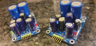
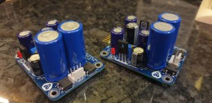
Got a couple of these little beauties done this weekend. Planning on using them on a pre amp. Was thinking about initially trying as is and then possibly followed by an ldo.
Fed with a 'healthy' 15vac trafo I'm getting 24 vdc at the first smoothing caps and have adjusted down to 19v so should be getting decent ripple reduction.
Nice little project. I made an error in getting one of the main bulk caps (I used 2200uf) wrong polarity. It soon fried the supply ac wiring and split open the smd BR! Won't do that again....oh wait....i probably will! Annoyed I transposed the black cap positions on the boards...symmetry and all that!
Attachments
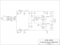
Ed Simon - Tracking Shunt Regulator
Ed Simon - Tracking Shunt Regulator
Custom Sound System Electronics Shop | Edward Simon & Co
Ed Simon - Tracking Shunt Regulator
Custom Sound System Electronics Shop | Edward Simon & Co
Attachments
Last edited:
Attachments
Last edited:
")
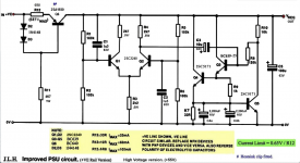
Perhaps something like this could be done for a small amp to drive headphones but replace the IRF610 with this unit (assuming there is a complementary p-channel)?
Another Juma creation:
About Diamond Buffer variations:
https://www.diyaudio.com/forums/solid-state/378269-diamond-buffer-variations.html#post6817544
Advantages and disadvantages?
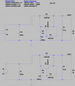
I made a small circuit for cap multiplier both for positive voltage npn and for negative voltage pnp. please see attached simulation file or picture.
They work great on simulation so i make the circuit.
The positive voltage and NPN is working great but pnp circuit with negative voltage is not working in real life what could be the reason of it?
They work great on simulation so i make the circuit.
The positive voltage and NPN is working great but pnp circuit with negative voltage is not working in real life what could be the reason of it?
Attachments
I made a small circuit for cap multiplier both for positive voltage npn and for negative voltage pnp. please see attached simulation file or picture.
They work great on simulation so i make the circuit.
The positive voltage and NPN is working great but pnp circuit with negative voltage is not working in real life what could be the reason of it?
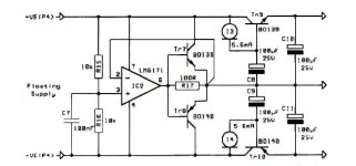
This cap multiplier (as a part of an rail splitter) works well, I3, I4 are 5.6mA Current Diodes - CDR
Last edited:
I made a small circuit for cap multiplier both for positive voltage npn and for negative voltage pnp. please see attached simulation file or picture.
They work great on simulation so i make the circuit.
The positive voltage and NPN is working great but pnp circuit with negative voltage is not working in real life what could be the reason of it?
What voltages are you measuring at the three terminals of the PNP? Are you sure the PNP is good and correctly installed? (Correct pin out?)
What exactly do you mean by not working? No output? Damaged/shorted PNP? No ripple rejection?
When I tried capacitance multipliers I found that the transistors were very quickly damaged by momentarily going outside the SOA. [Not the steady state operating conditions.] I ended up putting strings of three diodes across the transistor to protect it from momentary high Vce.
What is the voltage? What is the startup load and steady state load? Is such a small transistor suitable?
Hello kozard;
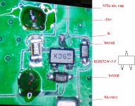
Pinout is correct. PLease see attached picture; i only consume 24ma that why i choosed small bjt.
All pins of transistor is -24 voltage. But the output 10u decoupling MLCC is -3V.
so i checked if mlcc is shorted to ground or not but it is not.
even i removed 10u cap still -3v so strange
Pinout is correct. PLease see attached picture; i only consume 24ma that why i choosed small bjt.
All pins of transistor is -24 voltage. But the output 10u decoupling MLCC is -3V.
so i checked if mlcc is shorted to ground or not but it is not.
even i removed 10u cap still -3v so strange
Attachments
Last edited:
Isn't the output the emitter? So how can the output be both -24V (at the transistor) and -3V (at the MLCC)?
Perhaps check again the soldering of the MLCC and the emitter? Then check the continuity from the transistor emitter lead (physical lead not the solder) to the top of the MLCC capacitor (again not the solder, the actual metalization on the capacitor).
Your schematic shows 0.1uF. No 10uF.
If it is a 10uF MLCC is it really rated for a high enough voltage? Many 10uF MLCC are lower voltage.
Finally, did you get the PNP, diodes and MLCC from a real authorized distributor or from eBay or AliExpress?
I bought a similar PNP (BC807) and I received a dual Schottky diode that didn't work too well in the circuit... I have also had ceramic capacitors that were supposedly 50V but failed at 24V (across +/-12V opamp supplies).
Do you have a M328 transistor tester with SMD pads? Can you hold one of the BC857 on the SMD pads and test it to make sure it is a real BC857? I sometimes use a pencil eraser to push down on an SMD when testing with the SMD pads.
I looked at a couple BC857 and saw simpler markings of only "3F" and "3G". (Maybe just different brand.)
I looked at a couple BC857 and saw simpler markings of only "3F" and "3G". (Maybe just different brand.)
- Home
- Amplifiers
- Power Supplies
- Juma's Easy-Peasy Capacitance Multiplier