There are other High Bandwidth Super Smoother designs (of which Cap multiplier is but one example), which get lower input-to-output voltage drop, in exchange for greater circuit complexity. You'll need a dummy load, an oscilloscope, and a function generator to dial in the correct values of frequency compensation components, and to dial in the just-barely-not-defecating-the-bedsheets input to output voltage drop. But if it's really important to you, I mean Really Important, then high complexity, large PCB area, super fiddly tuneup circuitry, can reduce your voltage loss.
My own experience with all cap Mx is that with a real load connected and an O-scope to look at input sawtooth and output sawtooth leaking through, I have to adjust the droput to quite a bit - like 3.7V drop to get the sawtooth down to about 2.5mVrms with 280mVrms input. This is about -40dB of ripple control. The simple Juma one with no adjustments is about 4v drop and has very good ripple control. So now I am not so sure if adding all that complexity is helping anything. But basically, we are building a high power analog amplifier to regulate the voltage to keep the voltage flat independent of the input ripple. So having more components and more feedback will let one get closer to flat no ripple out.
Remember what is possible.
Remember that lots and lots of IC voltage regulators are available, with 200mV voltage drop from input to output, while simultaneously delivering >60dB rejection of input ripple {also called PSRR}. Expert circuit designers find it not terribly difficult to make regulators with even better performance, given the huge variety of discrete components available (a much richer palette than IC designers are allowed), even while delivering multiple amperes of output current. Non expert designers can possibly get quite good performance too, via cut-and-try scattershot approaches in simulation or lab testbench prototypes with measurements.
Also remember what is important. The First Watt M2 does not require, and does not benefit from, quiet supply rails. Fooling around with smoother supplies on the M2 is a complete waste of time. M2 is one of the reigning world champions of insensitivity-to-rails-noise LINK, thanks to its all-follower transistor circuitry and all-magnetic "VAS". So if you're building an M2 or M2 variant, forget about rail smoothing and enjoy the higher output power of ZERO DROPOUT, inactive, nonfilters. As Nelson Pass originally designed the M2.
I agree it’s very clever to use an autoformer devoid of rail supply ripple, but that transformer, without a mu-metal shield, picks up radiated hum from the nearby power transformer like flypaper picks up dust.
It may be free from hum induced by VAS rail supply ripple, but I would not call the M2 one of the champs of low noise from hum (in general) by any means. The specs by Pass states it at 600uV rms which is among the higher values. Without shielding and careful placement of power transformer vs autoformer location, I get >1.3mV rms noise on my M2. With mu-metal it was about 400uV.
For those powering SE Class A amps, power supply ripple is very important to control as it directly translates to audible hum.
Last edited:
And the First Watt M2 is not a SE Class A amp. M2 is a push pull class A amp. Power supply ripple is unimportant in the M2 as it has no impact upon hum. To reduce hum in an M2, use a double shielded power transformer and wrap a pair of metal faraday cages around the interstage coupling transformers.
I just started a GB for a simple single rail PSU with the MOSFET cap Mx and a voltage regulator. Good for single rail applications under 1amp.
GB for Simple Cap-Mx Regulated Low-Noise PSU
GB for Simple Cap-Mx Regulated Low-Noise PSU
Hi Prasi! Could it possible to ask for Gerbers for this beauty?with new and improved features!
Hello Alexbio,
Here are the gerbers , schematic and stuffing guide for the design.
simply saw off the excess portion near ac connection, if you dont need it.
regards
Prasi
Here are the gerbers , schematic and stuffing guide for the design.
simply saw off the excess portion near ac connection, if you dont need it.
regards
Prasi
Attachments
I am working with Jofland on offering a new Cap Mx PSU board that includes the LT4032 active bridge rectifier, a CRC, and a cap Mx as the ultimate low noise cap Mx PSU. It will be offered as a GB as soon as I get the layout sorted out. We have a working single rail version and it sounds fantastic on a SE CLass A amp running up to 5amps. There is almost no heat generated from the bridge. Plus, it switches at zero crossover, so the noise spikes from switch on/off are minimal. It sounds quieter - there is a difference. Plus, you get extra voltage headroom as there are no 0.6v silicon diode dropouts.
Stay tuned...
Stay tuned...
The SLB (Smooth Like Butter) active bridge rectifier : CRC / Cap Mx PSU thread is here:
The SLB (Smooth Like Butter) Active Rect/CRC/Cap Mx Class A Power Supply GB
The SLB (Smooth Like Butter) Active Rect/CRC/Cap Mx Class A Power Supply GB
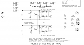
This is great forum and has been very helpful. I just order some W204011ASH1
W61084ASN2_juma cap multi boards from PCBway! I am planing to modify one of the boards by adding a TL431 to add regulation and compensate for the difference in the Vgs of the mosfets.
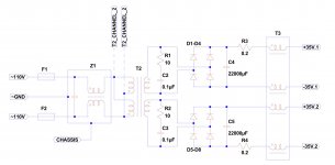
I have one question about the original design. Do the diodes D1, D2, D4 and D5 eliminate the need for zener clamp between gate and source of the MOSFETs?
W61084ASN2_juma cap multi boards from PCBway! I am planing to modify one of the boards by adding a TL431 to add regulation and compensate for the difference in the Vgs of the mosfets.
I have one question about the original design. Do the diodes D1, D2, D4 and D5 eliminate the need for zener clamp between gate and source of the MOSFETs?
Attachments
- Home
- Amplifiers
- Power Supplies
- Juma's Easy-Peasy Capacitance Multiplier