As Mark said really, a logic level low Rds device. This is the PSMN1R025YLD.
Looks good")
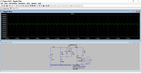
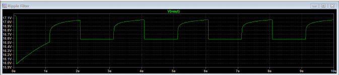
Ripple at 1.7 amps steady state and pulsed 1.7 amp.
I've attached the spice file set up for the IRF240 which will run straight off in LT IV. The PSMN1R025YLD FET model might only be available in LT XVII
Looks good
Ripple at 1.7 amps steady state and pulsed 1.7 amp.
I've attached the spice file set up for the IRF240 which will run straight off in LT IV. The PSMN1R025YLD FET model might only be available in LT XVII
Attachments
That PSMN1R025YLD looks like an awesome FET, however it has 25v limit which sort of limits it to 15v class A head amps or maybe preamps. A 25v typical class A supply might be too much. I like the 890 microOhm Rs_on, and continuous 100A!
This could be a very useful little FET to make a cap multiplier for my F5 head amp.
http://datasheet.octopart.com/PSMN1R0-25YLD-NXP-Semiconductors-datasheet-62336464.pdf
Is the input capacitance too large to use it as an audio OPS?
This could be a very useful little FET to make a cap multiplier for my F5 head amp.
http://datasheet.octopart.com/PSMN1R0-25YLD-NXP-Semiconductors-datasheet-62336464.pdf
Is the input capacitance too large to use it as an audio OPS?
Last edited:
The capacitance shouldn't be much of a problem at audio frequencies, and these things are meant to be used at high speeds in DC/DC convertors and so on.
Wouldn't like to say just how suitable it would be overall though but it could make for an interesting project. Maybe there are other higher voltage devices available in a similar series of parts.
Wouldn't like to say just how suitable it would be overall though but it could make for an interesting project. Maybe there are other higher voltage devices available in a similar series of parts.
The driver has to be able to both charge and discharge the gate capacitance and so a few milliamps need to be available.
Perhaps something like this could be done for a small amp to drive headphones but replace the IRF610 with this unit (assuming there is a complementary p-channel)?
Another Juma creation:
Thanks, Jason. I don't know enough to understand why it has so many transistors though - are there added benefits like lower dripeout voltage or better ripple control vs the Juma "Easy Peasy" circuit? I submit, the Juma circuit is dead simple, still.
You grabbed the schematic from post #1, not the final version in post #65. You won't like it though since it is more complicated yet again
.Lower 'drop-out' is possible with normal Vgs devices since they operate common source rather than as a follower. Two pole filtering reduces ripple a fair bit over the usual single pole.
Juma's arrangement is a pretty classic implementation.
Perhaps something like this could be done for a small amp to drive headphones but replace the IRF610 with this unit (assuming there is a complementary p-channel)?
I don't see why not although as always, it would be advisable to do some real measurements and weigh up the pros and cons compared to more traditional devices.
I just ran some sims in TINA and see that this cap multiplier can really save one some money with the cost of big caps. For example, if I simply removed my CRC consisting of a 33mF//0.12R//33mF and replaced it with a single 33mF and then couple that to the cap multiplier - it still works well with probably 100uV ripple with a 2amp steady load. So right there, one can eliminate qnty 4 x 33mF caps in a class A PSU. That's a significant savings in money and volume needed inside the case.
Guess why people like cap multipliers in this application...
Just be careful not to optimize dropout voltage too much, or otherwise it might drop out of regulation given high input ripple. Less of a problem with MOSFETs, more so with BJTs.
I am not sure what you are saying here. If we optimize for low driput, it might not regulate ripple well?
I am not sure what you are saying here. If we optimize for low driput, it might not regulate ripple well?
Yes. Just do not make the pass transistor saturated. Mosfet with low RDS-on can have low saturated voltage. I use BJT because it is easly to find here, and I set dropout voltage is 4V minimum.
If you use an averaging voltmeter to measure a DC voltage, the reading is the average of that DC.I am not sure what you are saying here. If we optimize for low driput, it might not regulate ripple well?
When there is ripple or interference superimposed on that DC the averaging voltmeter reads outs the same DC voltage.
But the actual voltage is the DC ± (half the ripple peak to peak).
i.e. you measure 30Vdc on a constant DC supply.
Add on 2Vpp of ripple and you now have 29V to 31V, where your averaging voltmeter reads 30Vdc.
Now apply that to your regulator or to your capacitor multiplier.
Assume the output is 28.5Vdc
When the input is 31Vpk and the output is 28.5Vdc the main voltage dropping semiconductor has 2.5V across it. There is no problem with drop out.
When the interference/ripple is at the bottom of the dip the input voltage is only 29Vpk and the output voltage is 28.5Vdc. The semiconductor now has 0.5V across it. Is the circuit capable of working properly when the Vdrop is only 0.5V? If not then you have drop out or increased output impedance or some other loss of performance.
It's the worst case Vdrop that one must look at for any regulator or capacitance multiplier.
A BJT using a corrupted capacitance multiplier has a Vdrop of 1Vbe that's only ~0.6V
With typical ripple/interference superimposed on the input that main semiconductor will be in or very near drop out mode on every dip of input voltage whenever output current is demanded.
Adopt a correct capacitance multiplier and one uses the final resistor across the base filter capacitor to trim the Vdrop of the BJT. One uses this "trimming" feature of the resistor to ensure in worst case conditions that the cap multiplier does not drop out.
Now compare to a high Vgs mosFET used in a cap multiplier or regulator.
The Vdrop from input to output must be greater than Vgs of the mosFET device.
Vgs is typically 2.5V to 4.5V
Now the input cannot be 30Vdc for a 28.5Vdc output. One starts with a much higher input voltage because of the high Vgs. Typically one would use >32V ±50% of 2Vpp ripple, for a 28.5Vdc output.
The minimum input would be 31V and the output would be 28.5V leaving a Vdrop across the mosFET of 2.5V and a maximum of 4.5V
The mosFETs high Vgs has forced one to adopt a high margin that hides the inadequacies of the corrupted cap multiplier. But even here it is better to add in the trimming resistor across the last capacitor in the gate filter.
Last edited:
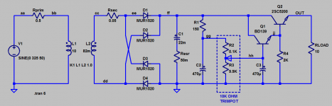
Which is why it's a good idea to include a 20 turn trimmer potentiometer in your circuit design, and then use an oscilloscope to measure your circuit's operation under worst case conditions (min Vin, max Iload). Dial the trimmer while watching the oscilloscope traces. Adjust until you achieve a balance between dropout voltage and safety margin that is acceptable to YOU. Done!
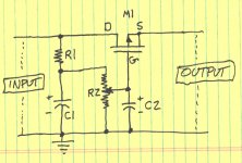
The schematic below would benefit from a very low threshold voltage NMOS FET like IRL640A. If your input ripple is small, this particular MOSFET can operate with quite low dropout voltage. If your input ripple is big, dial trimmer pot R2 until you get the safety margin you think you need. Done!
(I omitted the gate protection diodes et al, for clarity. Rod Elliott's web pages show them in detail.)
_
Attachments
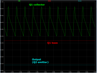
Here's a darlington version of a positive supply capacitance multiplier. I reduced BOM cost by downsizing the enormous bulk capacitor C1, from 47 millifarads (post #1) to 22 millifarads here.
Dropout voltage has been optimized through the use of a trimmer potentiometer; Vdropout = 1.3V. {input is 25.5V, output is 24.2V}.
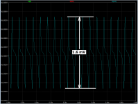
Output ripple is 1.6 millivolts.
I've chosen the 2SC5200 / 2SA1943 bipolar transistors for the output devices; their Safe Operating Area @ DC includes (5 amps @ 30 volts Vce), which is waaaay more than enough for the F5 amplifier with 2SK2013, as linked in post#1. Mount them on a hefty heatsink as shown in post #1, good to go.
_
Dropout voltage has been optimized through the use of a trimmer potentiometer; Vdropout = 1.3V. {input is 25.5V, output is 24.2V}.
Output ripple is 1.6 millivolts.
I've chosen the 2SC5200 / 2SA1943 bipolar transistors for the output devices; their Safe Operating Area @ DC includes (5 amps @ 30 volts Vce), which is waaaay more than enough for the F5 amplifier with 2SK2013, as linked in post#1. Mount them on a hefty heatsink as shown in post #1, good to go.
_
Attachments
Thanks Mark. I will give it a try - I agree you don't need the 47mF and huge BOM savings with the above setup. That's a nice low dropout voltage. 33mF Cornell Dubelier caps are not very expensive and will give quite a bit better ripple control. Also I did sim with 2.2mF inside instead of 470uF or 220uF and that helps a lot. I get maybe 150uV ripple with 2amp load as I recall.
Assume the worst power amp ever conceived: an amplifier with ZERO power supply rejection ratio. Every millivolt of ripple on the supply rail, becomes a millivolt of ripple at the loudspeaker. Then 1.6mV peak-to-peak ripple is 0.6mV RMS into the speaker. Power delivered into an 8 ohm load is 45 nanowatts: 45 billionths of a watt. A very quiet sound.
Member
Joined 2009
Paid Member
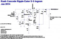
I'll add my 2c then....
http://www.diyaudio.com/forums/power-supplies/258464-rush-cascode-regulator.html
http://www.diyaudio.com/forums/power-supplies/258464-rush-cascode-regulator.html
Attachments
- Home
- Amplifiers
- Power Supplies
- Juma's Easy-Peasy Capacitance Multiplier