Hi there, I built a guitar preamp which runs off a 9 volt DC. I have a TDA7923 chipamp which runs off +-28VDC bipolar. I have attached a diagram showing this.
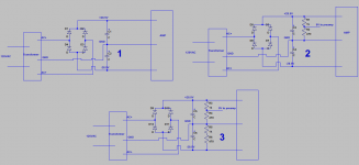
They are both in the same case, but there is a battery sitting there for the preamp. The preamp I think only uses a few milliamps according to ltspice simulation, so my first thought was to make a voltage divider. I did this and got 9 volts with 20ma going through the voltage divider (10x's the current draw from the preamp). That is shown as circuit labelled 2. It works, but very noisy. In fact the preamp doesn't have to be even hooked up. The mere presence of the voltage divider from positive 28.5VDC to ground caused significant noise, too annoying to be usable.
My second idea was maybe to put another voltage divider from 0 to -28.5VDC just to make sure one side isn't being loaded causing some problem but I have not tried this yet.
I have also heard about the LM317 adjustable voltage regulator but have not used it, I don't know if that is a good thing to try. But even if I use that and its placed from +28.5VDC to GND, I'm wondering if it will cause noise also. (I'm not talking about the LM317 being noisy, because I hear its great) Rather, I have a relatively quiet amplifier section, which when 1.47k is placed from the positive to ground on the power supply becomes noisy.
Is using a voltage divider this way just a bad idea or is there something I can do to make it work?
My other thought was to put the voltage divider 1k/470 ohm from +VDC to GND on power supply, then put a 2k trimpot from GND to -VDC and try and match the resistance exactly, would that do anything?
What do people usually do when they need to power a small second lower voltage device from a larger power supply powering an amp?
Attachments
Last edited:
What do people usually do when they need to power a small second lower voltage device
from a larger power supply powering an amp?
Usually a 3 pin regulator is the best choice. Use a 10uF capacitor at its output.
https://www.fairchildsemi.com/produ...ositive-voltage-linear-regulators/LM7809.html
Sometimes you can use a series resistor to drop the voltage, if the current draw is constant.
You'd need to use a filter capacitor after the resistor as well.
Last edited:
Do i supply the regulator from the top voltage rail in the bipolar power supply to ground?
Also i just thought of this but is there any role for a zener diode to drop the voltage?
The HV positive voltage goes to the regulator input pin, usually pin #1. Usually pin #2 is ground.
The output pin #3 would have a 10uF capacitor to ground, and the LV circuit. A heat sink
on the regulator might be necessary for higher load currents.
http://www.electro-tech-online.com/attachments/screen-20shot-202014-01-01-20at-2014-48-47-png.83152/
A series resistor with a Zener to ground can have a similar function for lowish currents,
but is somewhat trickier to design due to tighter constraints on the Zener current.
A Zener diode requires a certain minimum level of current to begin to regulate adequately.
Zener Diode as Voltage Regulator Tutorial
Last edited:
Built with 9.1 Volt Zener diode, can anyone explain why this inductor reduced hum?
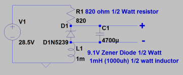
Hi there, I went with the zener diode idea. I've attached the circuit. For anyone interested who hasn't seen this I'll spell out what I did. I have a 1/2 watt 9.1V zener diode.
1/2 watt/9.1V = 55ma
resistor needed to make 55ma:
24.5V-9.1V= 20.5 V is voltage across resistor.
20.5/.055 amp = 372 ohms, round up to 390 ohms
However, the power dissipated by that resistor is 1.077 watts.
I doubled that to 780, round up to 820, to use a 1/2 watt resistor.
Now the current going through the resistor and zener diode is 25ma (20.5V/820= 25ma)
My preamp uses 2.5ma, so the current across the zener/inductor is 10xs that, so the load won't effect the voltage much, so that all works out.
However after building it, there was a good amount of hum, I think because the amplifier module I have is not filtered well, it only uses 2200uf capacitors on the power supply.
So I added a 4700uf 16V capacitor across the 9.1 volt supply, that really didn't do a whole lot, but I left it there.
I had some 100mh 100ma inductors, so I tried putting that in the circuit in various places, above the zener above the resistor, on the voltage tap itself and on the ground.
For whatever reason, when placed between the ground and the zener, it took care of the hum pretty much entirely.
I also had some 1mh inductors, 1/2 watt and replaced the 100mh inductor with a 1mh inductor.
That too took care of the hum issue.
So the setup sounds fine, but does anyone know what the inductor is doing to reduce hum, and also why placing it to the ground is the only spot where it was effective.
Also, notice I had to put the "negative" tap to the 9.1 volt power supply above the inductor, placing it below didn't work.
The inductor is 11 ohms resistance so the bottom of the 9.1 volt supply is very near ground.
(Also, I accidentally used a 1/4 watt resistor instead of 1/2 watt, so I guess I will have to replace this, but it hasn't blown yet.)
Attachments
why placing it to the ground is the only spot where it was effective.
You could have a ground loop, try a 10R instead of the inductor to ground.
If that does just as well, try grounding the Zener to a different point.
Ok, I will try that. I will have to take a break from building it for a few days. Thank you for your help.
CAn you post some photos of the circuits?
Here is a post I just put up of the preamp, but I will have to get back in a few days to show a circuit of the amplifier section and power supply to the preamp.
http://www.diyaudio.com/forums/inst...-any-advice-my-point-point-preamp-design.html
http://www.diyaudio.com/forums/inst...-any-advice-my-point-point-preamp-design.html
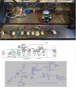
Here is the circuit I am powering with wiring diagram
Hi rayma
Here is the preamp I am powering off the power amp supply.
I have one question though. The first thing I tried was a simple voltage divider with 10x's the current going down the divider as the circuit takes. It did work, but even noisier than the zener circuit, so I scrapped it. This may have been a ground loop issue also.
Question is, is there any reason to not use a simple voltage divider?
Thanks for your help, gary
Attachments
is there any reason to not use a simple voltage divider?
You could do that, if you also use a large electrolytic capacitor of around 100uF or more,
from the 9V node to ground. This will work if the load circuit draws a small DC current
compared to the divider, and also if the large capacitor bypasses the AC current of the
load circuit to ground.
Last edited:
Ok om going to go back and retry this because i always use the simplest thing. If i can make a circuit with 2 resistors and 1 cap, or 1 resistor 1 cap and 1 zener diode, im picking the former just outbof simplicity.
About the ground loop issue, it sounds to me like i need to lift the ground at the power amp input which I inadvertently did when i lifted the input, output, and power grounds by 10 ohms or so.
So im actually very happy with the amp as is, but im going to disassemble and retroubleshoot (if thats a word) and find the simplest fix.
Im pretty sure though the voltage divider was noisier than the zener setup without any ground lift employed. But it did work. Will repost after i get back into the dungeon/lab.
Zener vs. voltage divider
So just for curiosity i tested a zener diode circuit vs a simple voltage divider with 10xs the current being drawn from the load. At the output i also put a 470 uf capacitor. Essentially both were acceptable but there was a little more noise on the voltage divider, suble but present. The hum from the voltage divider supply sounded almost identical with the subtle additions of some higher frequency hums which i suppose might be some harmonics. Technically the voltage of the voltage divider changes slightly with the current draw/or load resistance so im not sure if im hearing that effect or if theres something internally about how the diode works that is doing this. Anyhow the voltage divider was usable/acceptable but just a little worse. To test i had everything on amp maxed out with no input signal and listened by ear.
So just for curiosity i tested a zener diode circuit vs a simple voltage divider with 10xs the current being drawn from the load. At the output i also put a 470 uf capacitor. Essentially both were acceptable but there was a little more noise on the voltage divider, suble but present. The hum from the voltage divider supply sounded almost identical with the subtle additions of some higher frequency hums which i suppose might be some harmonics. Technically the voltage of the voltage divider changes slightly with the current draw/or load resistance so im not sure if im hearing that effect or if theres something internally about how the diode works that is doing this. Anyhow the voltage divider was usable/acceptable but just a little worse. To test i had everything on amp maxed out with no input signal and listened by ear.
The 1k resistor feeding a 9V Zener in parallel with a 100uF to 1000uF x16 or 25V capacitor is the classic solution.
Your preamp can take *up to* 20 mA and that supply is very clean, so if you have hum/buzz/squeal problems it´s because of grounding problems.
Don´t worry, grounding is a sort of black art which you learn by building.
Most beginner projects hum/hiss/buzz/etc. , even if they seem to be following the rules, main problem is that ground in general is "dirty" so grounding "here" is noisy, grounding "there", maybe 1 inch away, is silent.
After some time you learn and know how and where to ground and after even more time, you don´t even think about it, you just do it the right way.
Compare it to driving")
Your preamp can take *up to* 20 mA and that supply is very clean, so if you have hum/buzz/squeal problems it´s because of grounding problems.
Don´t worry, grounding is a sort of black art which you learn by building.
Most beginner projects hum/hiss/buzz/etc. , even if they seem to be following the rules, main problem is that ground in general is "dirty" so grounding "here" is noisy, grounding "there", maybe 1 inch away, is silent.
After some time you learn and know how and where to ground and after even more time, you don´t even think about it, you just do it the right way.
Compare it to driving
So just for curiosity i tested a zener diode circuit vs a simple voltage divider with 10xs the current being
drawn from the load. At the output i also put a 470 uf capacitor. Essentially both were acceptable.
Make sure the Zener diode under worst case conditions will have more than 10% of its rated current
(rated power/voltage), to ensure regulation.
Ok thanks rayma. I also read to set the resistor so that the current at 70% the
maximum current where imax=power rating/zener voltage.
The ideal operating Zener current is around 40% of the max current for the best thermal stability.
If the Zener is in a hot environment above 50C, you'll also have to derate the max current.
- Status
- This old topic is closed. If you want to reopen this topic, contact a moderator using the "Report Post" button.
- Home
- Amplifiers
- Power Supplies
- Preamp section unipolar 9v, Amp section +-28.5V bipolar, how to power both?