powering the Raspberry Pi + DAC with this cooler Ssr Aluminium Koellichaam 25A 30A Zilver Tone Solid State Relais Heatsink Radiator Voor Eenfase SR W|Relais| - AliExpress
So far no issues...playing for hours without heating up too much. a little bit warm but no problem to touch it constanly. I guess around 45 degrees C. Very happy and good sound
So far no issues...playing for hours without heating up too much. a little bit warm but no problem to touch it constanly. I guess around 45 degrees C. Very happy and good sound
Interesting.!
Why not try the film caps over the rectifier diodes...quite an easy one to do.
I tried those (10nF) and found that it made the sound too edgy, not natural, so yanked them. I also tried a 0.1uF and then a 1uF poly across the smoothing cap. While I really liked the HF detail on that, somehow it seemed to suck out the mid and bass response. So I've gone back to no film bypasses on diodes or smoothing cap.
I did find eventually that the diodes were deficient. When I replaced with SBYV27 the leading edges of notes were a bit too sharp, so went back to SB560 (but new) and the sound was more natural with a good balance and right amount of sparkle. BTW: each time I had to run it in with the new diodes for 2-3 days before the sound settled.
I also changed out the 470uF cap near output to an Elna Silmic. Nice sound but seemed a little too soft. Then went to a Nichicon FG which seems good, slightly better the Panny FM I had first.
At the start I changed the Wima MKS at output to a Mundorf Supreme EVO. (The board says it should be a Wima MKP10 but MKS4 was supplied in the kit.
heatsink data collected for powering Raspberry Pi with neo Studer 900
Sorry for the long delay but other projects got in the way... for a while.
I set up the heatsink monitoring system with an LM35 thermistor (in TO-220 package) screwed to each heatsink.
The LM35's are connected to analog pins on an Arduino Pro Mini which has a software serial connection to an ESP8266 WiFi module to post the temperature to a web page I set up for that purpose.... saving it to a SQL database and correlating it to the Volumio player state through the Volumio API.... "off" (no power), paused, playing, or stopped.
See this post for the power supply setup.
The side with the larger heatsink powers the Raspberry Pi 4 running Volumio. That heatsink gets clamped tightly to the aluminum enclosure.
The side with the smaller (but still 25% larger than the standard) heat sink powers a MiniSharc DSP board. I don't get player info from that but can get some indication of its state via the Volumio status recorded along with temperature.
I believe the MiniSharc requires a 500 mA 5V power supply but I may not be remembering correctly.
With that setup, the MiniSharc PS's heat sink is actually the warmer of the 2, maxing out at around 120 degrees F and 50 degrees C. Even when playing music steady for hours, the heatsink for the side powering the Pi stays under 120 degrees F and 50 degrees C.
I hope that's helpful for others wanting to power a Pi with this supply.
If there's interest in replicating or getting more specific ideas from this setup I would be happy to provide more info...
I took a lot of pics and kept thorough notes so could share those along with the Arduino code for the Pro Mini and ESP8266.
I used C#/.NET and MS SQL for the web page collecting the data (it's sent with a querystring from the ESP8266) but using a REST API would likely be simpler.for most .. I'm just faster at .NET as that's what I use for most client web projects. If others have the electronics skills but not the programming know-how, I might set up a data collecting page others could use for similar projects.
Let me know if there's interest and I'll share more or maybe just knowing what I shared here will give enough confidence to Pi Powering Audioheads.")
Have you consider bolting the MJE15034 to the aluminum case bottom directly to get better heatsink effect? You seem to have enough space for that in your picture.
Hope to see your heatsink temp monitoring system result soon. For the mean time, can you take a reading of the heatsink/case top contact point temperature with an IR thermometer?
Sorry for the long delay but other projects got in the way... for a while.
I set up the heatsink monitoring system with an LM35 thermistor (in TO-220 package) screwed to each heatsink.
The LM35's are connected to analog pins on an Arduino Pro Mini which has a software serial connection to an ESP8266 WiFi module to post the temperature to a web page I set up for that purpose.... saving it to a SQL database and correlating it to the Volumio player state through the Volumio API.... "off" (no power), paused, playing, or stopped.
See this post for the power supply setup.
The side with the larger heatsink powers the Raspberry Pi 4 running Volumio. That heatsink gets clamped tightly to the aluminum enclosure.
The side with the smaller (but still 25% larger than the standard) heat sink powers a MiniSharc DSP board. I don't get player info from that but can get some indication of its state via the Volumio status recorded along with temperature.
I believe the MiniSharc requires a 500 mA 5V power supply but I may not be remembering correctly.
With that setup, the MiniSharc PS's heat sink is actually the warmer of the 2, maxing out at around 120 degrees F and 50 degrees C. Even when playing music steady for hours, the heatsink for the side powering the Pi stays under 120 degrees F and 50 degrees C.
I hope that's helpful for others wanting to power a Pi with this supply.
If there's interest in replicating or getting more specific ideas from this setup I would be happy to provide more info...
I took a lot of pics and kept thorough notes so could share those along with the Arduino code for the Pro Mini and ESP8266.
I used C#/.NET and MS SQL for the web page collecting the data (it's sent with a querystring from the ESP8266) but using a REST API would likely be simpler.for most .. I'm just faster at .NET as that's what I use for most client web projects. If others have the electronics skills but not the programming know-how, I might set up a data collecting page others could use for similar projects.
Let me know if there's interest and I'll share more or maybe just knowing what I shared here will give enough confidence to Pi Powering Audioheads.
Last edited:
Side note on the above post...
If the Raspberry Pi has Volumio installed, it would be fairly trivial to automatically shut things down if it starts to get too hot. ... add an if-then to the Arduino code to send a shutdown command to Volumio from the ESP8266 if the temperature gets above X.
Cheers
Chris
If the Raspberry Pi has Volumio installed, it would be fairly trivial to automatically shut things down if it starts to get too hot. ... add an if-then to the Arduino code to send a shutdown command to Volumio from the ESP8266 if the temperature gets above X.
Cheers
Chris
Hello All,
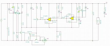
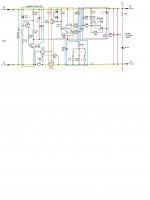
I am playing with this Regulator for my NanoPi M4 Music Server that require 5V4A power source (with storage module), base on the detail explain by bButcher, I can have the expected result in simulation with some tweaks, But I do not have electronic background therefore I would be nice if someone help me to validate some of my thoughts as:
1. I use TLE2072 as replacement for TL072, It should be better as TLE2072 is Direct Upgrades to TL072 as in datasheet statement? This is high speed opamp, I wonder if I need some special layout with capacitor between supply rails or just 100uF capacitor as the chinese kit is enough?
2. I use the GLED431 for voltage reference, As I understand the GLED431 using LED + Vbe for 2.5V voltage reference and Moreover, GLED431 established the CCS for LED so that It is much better than simple LED as voltage reference?
3. For the op-amp supply power, I re-config by using the LTP for better noise filter, Is It worth in this PSU?
4. For the 5V4A requirements, It seem that I need a transformer 6.3VAC@5A that is 9VDC and then for 5V4A, the power dissipation will be 16W ( or 14.4W as in simulation), It mean that I need heat sink with capability at least 1K/W for 14.4°C above the environment temperature ?

I attached my TINA-TI simulation file and screenshot of the results!
Thank in advance!
HT,
I am playing with this Regulator for my NanoPi M4 Music Server that require 5V4A power source (with storage module), base on the detail explain by bButcher, I can have the expected result in simulation with some tweaks, But I do not have electronic background therefore I would be nice if someone help me to validate some of my thoughts as:
1. I use TLE2072 as replacement for TL072, It should be better as TLE2072 is Direct Upgrades to TL072 as in datasheet statement? This is high speed opamp, I wonder if I need some special layout with capacitor between supply rails or just 100uF capacitor as the chinese kit is enough?
2. I use the GLED431 for voltage reference, As I understand the GLED431 using LED + Vbe for 2.5V voltage reference and Moreover, GLED431 established the CCS for LED so that It is much better than simple LED as voltage reference?
3. For the op-amp supply power, I re-config by using the LTP for better noise filter, Is It worth in this PSU?
4. For the 5V4A requirements, It seem that I need a transformer 6.3VAC@5A that is 9VDC and then for 5V4A, the power dissipation will be 16W ( or 14.4W as in simulation), It mean that I need heat sink with capability at least 1K/W for 14.4°C above the environment temperature ?
I attached my TINA-TI simulation file and screenshot of the results!
Thank in advance!
HT,
Attachments
I re-post the pictures:
hi, I'm happy to see your schematics and tweaks,..but on my studer900 board some pins of bc140 are mixed up,....pins 1 and 2 (emitter/collector) are mixed up!!!,
on the Chinese board those pins are not consistent with your schematics!,...can you have a look at your board and confirm the mistake?
thank you.
best.
Your scheme looks different from the design posted before. Any reason why?Hello All,
I am playing with this Regulator for my NanoPi M4 Music Server that require 5V4A power source (with storage module), base on the detail explain by bButcher, I can have the expected result in simulation with some tweaks, But I do not have electronic background therefore I would be nice if someone help me to validate some of my thoughts as:
1. I use TLE2072 as replacement for TL072, It should be better as TLE2072 is Direct Upgrades to TL072 as in datasheet statement? This is high speed opamp, I wonder if I need some special layout with capacitor between supply rails or just 100uF capacitor as the chinese kit is enough?
2. I use the GLED431 for voltage reference, As I understand the GLED431 using LED + Vbe for 2.5V voltage reference and Moreover, GLED431 established the CCS for LED so that It is much better than simple LED as voltage reference?
3. For the op-amp supply power, I re-config by using the LTP for better noise filter, Is It worth in this PSU?
4. For the 5V4A requirements, It seem that I need a transformer 6.3VAC@5A that is 9VDC and then for 5V4A, the power dissipation will be 16W ( or 14.4W as in simulation), It mean that I need heat sink with capability at least 1K/W for 14.4°C above the environment temperature ?
I attached my TINA-TI simulation file and screenshot of the results!
Thank in advance!
HT,
I want to power Rpi4 + external 2,5" HD. When I draw 2A the power drops to 0,5V. input volt drops from 10,2 VAC to 9,4 VAC.
I tried different transfo (9v/1,66A) (2x9V/1,66A) (9V/2,78A) all the same result.
Also tried to combine the output from my dual board but still the same.
I try to investigate what is wrong but dont know where to start.
I changed R102 to 5K and R107 is 0,1 ohm.
Attachments
You are trying to draw too much current...
low noise Pre-Amp / DAC power supply MJE15034 TL072 Regulator based on STUDER 900
use the board to power the Pi and use a USB powered hub between the Pi and the USB drive.
low noise Pre-Amp / DAC power supply MJE15034 TL072 Regulator based on STUDER 900
use the board to power the Pi and use a USB powered hub between the Pi and the USB drive.
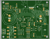
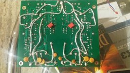
Hello I have used this PCB for my Replica Borbely MC Pre Phono.
I have tweaked it with some good components and put wire for the High current line.
It is very silent.
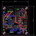
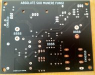
Since it works good I have redesigned the board keeping in mind, place for bigger Eletrolytics and bigger traces.
Next time I will try Some modification you suggested.
I have tweaked it with some good components and put wire for the High current line.
It is very silent.
Since it works good I have redesigned the board keeping in mind, place for bigger Eletrolytics and bigger traces.
Next time I will try Some modification you suggested.
Attachments
Hello I have used this PCB for my Replica Borbely MC Pre Phono.
I have tweaked it with some good components and put wire for the High current line.
It is very silent.
Since it works good I have redesigned the board keeping in mind, place for bigger Eletrolytics and bigger traces.
Next time I will try Some modification you suggested.
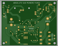
Good on you, and done on the same board size! Did you get better results in modelling and better results when you built it?
I notice some of the high current traces in the lower layer don't seem to have much clearance from traces next to them.
It is almost the same board size. I have not yet bulit it, because I am on holiday.
It should work fine , because one big problem were the thin copper lines and I had always to put wire point to point.
I cannot measure anything about noise. When I will try I will post something. Clearance is 12 mil.
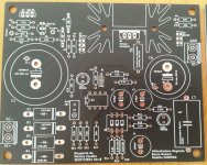
I just want to avoid doing this:
It should work fine , because one big problem were the thin copper lines and I had always to put wire point to point.
I cannot measure anything about noise. When I will try I will post something. Clearance is 12 mil.
I just want to avoid doing this:
Attachments
Max current
I have tried today to verfy the maximum current this circuit can deliver.
So I have set up the output voltage to 18 VDC.
POwer transformer is a 100VA dual 15AC with max 3.33 A for both secodary pair.
I have removed R111 to not limit Vce of the power bjt Q104 ( in my case TIP31C Ic max 3 A).
Then I have shorted R109 .
The BD140 (Q105) which control the base of Q104 has two diodes with limit its Vbe. I have removed one of them.
Well with 50W Load resistor 8.2 Ohm and 18VDC I expected 2.19A...but the regulator could rech just ca 15V...and the BD140 was getting very hot. I have turned of the circuit otherwise it would have been burnt.
This BJT schould pump current in the base of the power BJT.... but it can´t and it becomes very hot...
I do not understand what is happening. can someone help?
The limit resistor is 0.22 Ohm
I would reach 4 A of course with a D44H11... but there is this limitation which I do not understand. Thanks
Your scheme looks different from the design posted before. Any reason why?
I want to power Rpi4 + external 2,5" HD. When I draw 2A the power drops to 0,5V. input volt drops from 10,2 VAC to 9,4 VAC.
I tried different transfo (9v/1,66A) (2x9V/1,66A) (9V/2,78A) all the same result.
Also tried to combine the output from my dual board but still the same.
I try to investigate what is wrong but dont know where to start.
I changed R102 to 5K and R107 is 0,1 ohm.
You need t remove teh 1N4148 diode otherwise is the base current of BD140 limited and it cannot open the MJE15034 any more.
At the same time you had to remove the block on the Vce of the MJE15034:
short R109 and open R111.
You will reach 2 A without any difficulties.
- Home
- Amplifiers
- Power Supplies
- low noise Pre-Amp / DAC power supply MJE15034 TL072 Regulator based on STUDER 900