Hi All,
I just found out bout this LPS today. I want to buy one and ask my friend to make it.
It will power my hard drive enclosure, It needs 12V/2.5A.
What transformer should I get? Any other changes in resistor than the default one?
Thanks
The L-Adapter by Salas suits your need better.
The L-Adapter by Salas suits your need better.
What is the difference with Studer? Which one is better? I'm planning to add HPULN LT3045 to the power supply. I heard this is is a very best combo.
Actualy I will need 12V @ 2A, so studer will work.
Thanks
Based on some seller on alienexpress says "The maximum current of the circuit is 1.5A. can't with 3-4A. Please pay attention to the use occasion, but the general preamp and decoding will not exceed 1A."
Lusya 5 24V STUDER900 Regulator Power supply board super LM317 LT1083 LT1085 DIY kit/finished board-in Amplifier from Consumer Electronics on Aliexpress.com | Alibaba Group
can someone confirm this? if it is true i wont be able to use it.
Thanks
Lusya 5 24V STUDER900 Regulator Power supply board super LM317 LT1083 LT1085 DIY kit/finished board-in Amplifier from Consumer Electronics on Aliexpress.com | Alibaba Group
can someone confirm this? if it is true i wont be able to use it.
Thanks
Based on some seller on alienexpress says "The maximum current of the circuit is 1.5A..."
can someone confirm this? if it is true i wont be able to use it.
If you are handy, you can increase the max current.
e.g. to get 2A output, remove D102 and D103. And change R107 to 0.33 ohms. Also check that the heatsink is capable for the power dissipation from your load (caused by the voltage difference between your transformer voltage and DC out voltage and the current draw of your load.)
See posts #73 to #93.
Thanks.
Now I am thinking about the alternatives Sigma 11 PSU.
The σ11 regulated power supply
Does anyone know which one is better?
Now I am thinking about the alternatives Sigma 11 PSU.
The σ11 regulated power supply
Does anyone know which one is better?
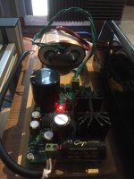
Received my board for about 10 days, use it to drive rbp 3b+ running moode connecting to an usb dac, the result is outstanding. So I spent some time study the circuit, run some simulation and do some mods on the board, here is some experience I would like to share:
(1) I modified the original circuit diagram to reflect where the clone board is different from the original one. Also each functional block is outlined with different colors.

*I forgot to change C105 to 47u for the clone board.
(2) Minimum 9V AC is required to properly power the board, since TL072 need at least 10V for Vcc+ - Vcc-.
(3) To configure the output voltage, use the following formula.
[Vout - Vin+] = Vref * (R127 + R126 + R125)/(R127 + R126min~max) = Vout * R115/(R115 + R119 + Rrange)
--- Rrange is the combined value of R122, R123, R301
--- Vref is voltage across reference red led DL301
with real values substituted,
[Vout - Vin+] = 1.938V ~ 2.193V ~ 2.525V, @Vref = 1.8V (usual forward voltage for red led)
and
Vout = Vref * (46.3k)(5.5k + Rrange)/(33k ~ 43k)(3.3k)
or tabularize the different combinations of Rrange:
Range__H___M____L____Vout (V), @Vref = 1.8V
2.5k____x____x____x_____4.70 ~ 6.12
2.7k_________x____x_____4.82 ~ 6.27
2.98k___x_________x_____4.98 ~ 6.49
3.3k______________x_____5.17 ~ 6.73
10.3k___x____x__________9.28 ~ 12.09
15k_________.x_________12.04 ~ 15.68
33k____.x______________22.61 ~ 29.46
Note: this is based on Vref = 1.8V, on my board the measured value is around 1.875, with L point soldered, the lowest reached voltage is 5.17*1.875/1.8 = 5.39, too high for 5V supply, I also have to solder M point to bring the output to 5V.
From the table, one can see it doesn't cover the full range, e.g. there is no way to adjust to 18V. In this case, you better install your own resistor use the following formula:
Rrange = {Vout/Vref) * (3.3k)(33k ~43k)}/(46.3k) - 5.5k
To generate 18V, Rrange = (18/1.8)*3.3*38/46.3 - 5.5 = 21.6k (use 21.5k standard 1% value). You can replace any of H, M, L resistors and with the corresponding point soldered on.
(4) About the maximal current it can supply, with some simulation (thanks to fabio1068 for the tina model)

From the simulation, the circuit start to fail between 1.67A to 1.83A. I'll suggest use it to drive at most 1.5A "peak" load.
(5) The noise figure: Since I only have a basic fluke multimeter and its minimal voltage resolution is 0.1mV, so this result is a rough estimation. After some modifications with the board, the following figures are measured.
rbp 3b+ + usb dac, music not playing, 0mV @terminal, 0mV @rbp 3b+ (< 50uV ?)
rbp 3b+ + usb dac + usb hard drive (use external usb hub swithing power), music not playing, 0.1mV@terminal, 0.1~0.2mV @rbp 3b+
rbp 3b+ + usb dac + usb hard drive (use external usb hub swithing power), music playing, 0.1~0.2mV@terminal, 0.2~0.5mV @rbp 3b+
*total current is about 0.5A
(6) The modifications I made on the board:
(A) The layout of the board is pretty bad, the measured resistance between input (right after rectifier diode) and output terminal (Vout) is around 14 mOhm, so I strengthen both power lines (yellow marked lines in the circuit diagram) with solid wires.
(B) Add 0.47u caps across the 4 input rectifier diodes.
(C) Earth the input ground (p1/8,9 in the circuit diagram) with a 0.01u cap.
(D) Use a line filter before the transformer.
(E) Change R102 from 10k to 5k. This is not about reducing noise, more about put 5.1V zener at proper operating point (~1.5mA), especially when drive the board with 9V AC.
The above is what I have done so far, hope my experience can help others.
Thanks for the measurements and especially the 5 volts I got this also basically at 5.41 volts and not lower but after soldering L and M now exactly at 5.02 volts.
thanks again.
Last edited:
I'm using this at 5v to drive my DAC, with a few capacitor changes. The detail is good with a good soundstage, but but noticed that the high notes (piano, cymbals, etc.) are a touch dull.Their tone is dull, lacking the musical sparkle of my other power supplies. @200+ hours. Any thoughts on what I might consider swapping out?
Substitutions @buildup
Substitutions @buildup
- Smoothing cap: Panasonic FR 2 x 5600uF. Also tried a Kemet ALS30 6800uF, which had slightly better bass but slightly worse HF detail.
- Wima Poly cap for Mundorf Supreme EVO.
- Striped 221 220pF for Kemet 221 220pF MLCC
Good to see interest still in this psu.
I power the IV stage of my Ian Canada dac with it.....best sound I've heard in my system.....although I haven't tried another psu here to be honest.
I have a Salas ubib 1.3 to build. I wander how much better than this studer 900 it will be....if any?
I am building another dual studer 900 for a streamer for my brother.
I have some elna 1000uf snap in for the main caps...I thought I may try in place of the 6800uf 'Nover'.
Do you think 1000uf is enough here?
Last edited:
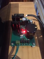
I've pimped mine with Mundorf & Nichicon caps and it sounds great. As a final touch I added vishay (0.01uF) bypass caps to the rectifier diodes and that is a nice improvement as well.
It looks like you didn't have room for the wirewound resistor. Is that mounted to the bottom?
I have some elna 1000uf snap in for the main caps...I thought I may try in place of the 6800uf 'Nover'.
Do you think 1000uf is enough here?
I'm neither an expert nor the son of one, but 1000uF is smaller than I've ever heard of for smoothing caps. I can't imagine it has much effect on stiffening the power supply or resisting ripple.
It looks like you didn't have room for the wirewound resistor. Is that mounted to the bottom?
Yes, the wirewound resistor is mounted on the bottom due to the size of the Nichicon caps. Likewise the rectifier diodes are mounted on the bottom to make room for the Mundorf cap to seat properly on the board giving a neater result in the end.
I'm neither an expert nor the son of one, but 1000uF is smaller than I've ever heard of for smoothing caps. I can't imagine it has much effect on stiffening the power supply or resisting ripple.
I'm guessing he means 10,000uF as that would be a reasonable substitute but could present mounting problems due to the larger physical size overlapping the rectifier diodes.
I'm guessing he means 10,000uF as that would be a reasonable substitute but could present mounting problems due to the larger physical size overlapping the rectifier diodes.
10,000 should be good. No one here has reported how the psu responds to the stiffness of 10,000 or higher. To be safe, I used a pair of Panny FR at 5600uF each. So the initial hit was meant to be 5600 but the total smoothing was 11,200. No idea whether that was helpful for this design.
When I used a Kemet ALS30 6800uF, I mounted the can on its side next to the board with wire jumpers to the board, and zip tied it down to the enclosure floor.
Morning guys.
I DID mean 1000uf but have since changed my mind. I was thinking 1000ug of Elna maybe better than an unknown 6800uf of 'Nover' but these are unfounded thoughts.
Whilst we are here....my dual board I am populating ....the 2 Rs at the end nearest the input. They are next to the 5V1 zener.? My board has 15R on the right hand silkscreem and 7.5 printed on the other rail.
My package contained no R15...only 15k. So I assume thos is a mistake. I do have the R7.5 but the fact it is different on the other rail confuses me.
Last edited:
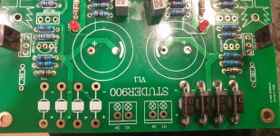
The 7.5R handles more current. 15R is only up to 1A and the 7.5R is meant to be up to 1.5A or so, per the seller.the 2 Rs at the end nearest the input. They are next to the 5V1 zener.? My board has 15R on the right hand silkscreem and 7.5 printed on the other rail.
My package contained no R15...I do have the R7.5 but the fact it is different on the other rail confuses me.
I have a Salas ubib 1.3 to build. I wander how much better than this studer 900 it will be....if any?
Depending on personal preference i would expect the sonic difference to be anywhere between very large and huge
")
Of course with the shunt regulator there are thermal penalties and current limitations.
See one rail has 7.5R and thr other has 15R
On my board both are 15R. I also have a single supply board which doesn't appear to use this resistor at all.
- Home
- Amplifiers
- Power Supplies
- low noise Pre-Amp / DAC power supply MJE15034 TL072 Regulator based on STUDER 900