Hello,
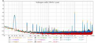
I did some measure of the ripple/noise of this regulator @5V output.
I do not have a professional measurement equipment, so I used my usb soundcard.
It is a Creative X-fi HD, modified as suggested here: Improving A/D perfromance of Sound Balster X-fi Music (SB1240) - and a Puzzle!!! - diyAudio
And I changed the coupling capacitor voltage to 35V.
I measured the voltage at different points of the circuit with 55ohm load at 5V (so 90mA) and at the output with no load, 90mA load, and 90mA load changing the opamp with a OPA2277. I also tried a OPA2134, but it did not behaved well, I think because the input is too close to the positive rail (only 1.9V, the voltage reference led).
In attachment you find the REW file and some screenshots.
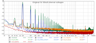
The images are the spectrum @96kHz sampling, FFT length=65536, average of 16 measures.
The 0dB of the ADC is 0.74Vrms, so they are dBu, more or less.
but the unit of the spectrum is not exactly dBu/sqrt(Hz).
Here after the RMS values in dBC:
(I write the dBC because the ADC has some high noise below 20Hz, so I think it is more meaningful than dBFS)
ADC noise floor -112.4 dBC
ZenerDiode -61.7
OPampRail -67.4
Led_Reference_Voltage -103
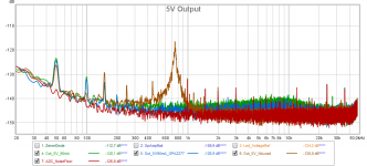
Output_5V_NoLoad -106.4
Output_5V_90mA -108.7
Output_5V_90mA_OPA2277 -110.3
So, if we consider the best measure at the output (-110.3 dBC) as dBu, it means more or less 2.4uV.
What do you think about the peak at 750Hz in the spectrum of the output with no load? It looks like, when the load is applied, it goes down and moves to higher frequencies, but it does not disappear completely
I did some measure of the ripple/noise of this regulator @5V output.
I do not have a professional measurement equipment, so I used my usb soundcard.
It is a Creative X-fi HD, modified as suggested here: Improving A/D perfromance of Sound Balster X-fi Music (SB1240) - and a Puzzle!!! - diyAudio
And I changed the coupling capacitor voltage to 35V.
I measured the voltage at different points of the circuit with 55ohm load at 5V (so 90mA) and at the output with no load, 90mA load, and 90mA load changing the opamp with a OPA2277. I also tried a OPA2134, but it did not behaved well, I think because the input is too close to the positive rail (only 1.9V, the voltage reference led).
In attachment you find the REW file and some screenshots.
The images are the spectrum @96kHz sampling, FFT length=65536, average of 16 measures.
The 0dB of the ADC is 0.74Vrms, so they are dBu, more or less.
but the unit of the spectrum is not exactly dBu/sqrt(Hz).
Here after the RMS values in dBC:
(I write the dBC because the ADC has some high noise below 20Hz, so I think it is more meaningful than dBFS)
ADC noise floor -112.4 dBC
ZenerDiode -61.7
OPampRail -67.4
Led_Reference_Voltage -103
Output_5V_NoLoad -106.4
Output_5V_90mA -108.7
Output_5V_90mA_OPA2277 -110.3
So, if we consider the best measure at the output (-110.3 dBC) as dBu, it means more or less 2.4uV.
What do you think about the peak at 750Hz in the spectrum of the output with no load? It looks like, when the load is applied, it goes down and moves to higher frequencies, but it does not disappear completely
Attachments
Hello,
I just bought this psu. My model is this:
STUDER900 amplifier Power supply board Finished board kit with heat dissipation-in Amplifier from Consumer Electronics on Aliexpress.com | Alibaba Group
Now I need transformer for it. My plan is to use this Studer900 psu with SOTM Sms-200 network streamer which needs 9VDC.
I contacted today my local electronics shop and they have one that has dual independent 15V secondaries (no center tapped) Could someone confirm that I can use one of those secondaries for PSU and adjust voltage to 9V? Or is 15V AC too much? Thanks for your time.
Oh, so much better than my simple multi-meter. I plan to order a Motu 624 to serve the same purpose, maybe I should just order a SB1240 and be done with it. Do you also change the op or just skip the switch? After the mod, can it really reach 105dB THD+N, have you done any loop back test?It is a Creative X-fi HD, modified as suggested here: Improving A/D perfromance of Sound Balster X-fi Music (SB1240) - and a Puzzle!!! - diyAudio
You should post this message earlier, I just ordered OP2134 yesterday, lol. That's fine, I also ordered lm336-2.5, so I can move the reference voltage to 2.5V or cascade another red led moving it to 3.7V. Before I placed the order, I did some simulation using OP2134, it seems working normally.... changing the opamp with a OPA2277. I also tried a OPA2134, but it did not behaved well, I think because the input is too close to the positive rail.
OPA2277 may have lower noise than TL072, but it is a little bit too slow to track fast change output load, (0.8V/uS slew rate, 1MHz GBW, compared to 13V/uS, 3MHz of TL072) so if you apply to real load I will expect TL072 will perform better than OPA2277 overall.
So, if we consider the best measure at the output (-110.3 dBC) as dBu, it means more or less 2.4uV.
Noise wise, it is very impressive. Don't know how its output impedance measured?
I did some simulation before, it didn't quite match your measured data. The feedback loop of error op did generate noise chart similar to your graph, but the peak value & frequency is very different. and it do move around with load.What do you think about the peak at 750Hz in the spectrum of the output with no load? It looks like, when the load is applied, it goes down and moves to higher frequencies, but it does not disappear completely
load........peak.freq...peak
10mA.........4.4k.......316nV
50mA.........7.5k.......637nV
100mA.......8.8k.......433nV
500mA.......8.5k.......670nV
1A..............6.6k.......337nV
It dose not appear at no load though, and if change 220p compensation cap to 9n.
load........peak.freq...peak
10mA.........750........180nV
100mA......1.43k......3300nV
1A.............1.08k.......190nV
Last edited:
OPA2277 may have lower noise than TL072, but it is a little bit too slow to track fast change output load, (0.8uV/uS slew rate, 1MHz GBW, compared to 13uV/uS, 3MHz of TL072) so if you apply to real load I will expect TL072 will perform better than OPA2277 overall.
I think there's a couple of 'u'-s too many in there...?
BTW Do you guys want to use FET input opamps only?
Jan
... dual independent 15V secondaries (no center tapped)
It might be too high. The voltage across Vce of pass transistor will be more than 10V, I assume your streamer will consume close to 1A, which will generate >10W at the heat sink.
@bButcher
about the SB1240, I bypassed the switch and changed the opamp (after I burnt the original opamp, trying to measure the voltage between a +-15V rail...") ).
).
So now the soundacrd has a 22uF 35V Nichicon bipolar cap, connected to a LM4562 opamp, with a 10ohm resistor between the two, in order to limit the peak current a little bit, without compromising the noise.
The LM4562 lower the noise floor a little compared to the original opamp.
I did not try a loop back test yet, but I think the results wold be limited by the THD+N of the DAC (around -90dB).
Regarding the OPA2134, I tried it on a modified regulator board with 2 diodes in series as reference voltage, and it works fine. I think that 2.5V between input and rails is the minimum recommended on the specs.
About the OPA2277, I noticed that the slew rate and the bandwidth was a little low, but I am not an electronic expert, so I do not know how important are those two parameter on a linear supply regulator. I thought that on a linear supply there is not much noise in the high kHz - low MHz range. I just chose it to try a BJT opamp that has not too much current noise, since the resistor on the input path are quite high. Maybe the OPA2134 is better.
@jan.didden do you think a BJT opamp would be better? In that case we should reduce the input resistors to get low noise, right? What do you think about the required slew rate and bandwidth?
@bButcher
About the output impedance of the regulator, I would not know how to measure it. Do you have a method to do it?
I was thinking to measure the ACvoltage spectrum when it is powering my katana DAC playing music, so I can see if I get the "music" in the spectrum of the power supply.
about the SB1240, I bypassed the switch and changed the opamp (after I burnt the original opamp, trying to measure the voltage between a +-15V rail...
).So now the soundacrd has a 22uF 35V Nichicon bipolar cap, connected to a LM4562 opamp, with a 10ohm resistor between the two, in order to limit the peak current a little bit, without compromising the noise.
The LM4562 lower the noise floor a little compared to the original opamp.
I did not try a loop back test yet, but I think the results wold be limited by the THD+N of the DAC (around -90dB).
Regarding the OPA2134, I tried it on a modified regulator board with 2 diodes in series as reference voltage, and it works fine. I think that 2.5V between input and rails is the minimum recommended on the specs.
About the OPA2277, I noticed that the slew rate and the bandwidth was a little low, but I am not an electronic expert, so I do not know how important are those two parameter on a linear supply regulator. I thought that on a linear supply there is not much noise in the high kHz - low MHz range. I just chose it to try a BJT opamp that has not too much current noise, since the resistor on the input path are quite high. Maybe the OPA2134 is better.
@jan.didden do you think a BJT opamp would be better? In that case we should reduce the input resistors to get low noise, right? What do you think about the required slew rate and bandwidth?
@bButcher
About the output impedance of the regulator, I would not know how to measure it. Do you have a method to do it?
I was thinking to measure the ACvoltage spectrum when it is powering my katana DAC playing music, so I can see if I get the "music" in the spectrum of the power supply.
No. I will try AD817 & AD825 later, but before I can do that I'll need to modify the board (remove fine tune opamp). Also I will need better measurement equipment to see the difference.BTW Do you guys want to use FET input opamps only?
Jan
The major reason I ordered OPA2314 is to lower opamp supply rail to ~5.5V so I can use 7V transformer. Less heat across pass transistor @ high current, right now when drive 5V load @ 1A, the hottest spot at the heat sink is about 70C.
Any suggestion for opamps to try? regardless BJT or FET input.
Last edited:
I would also suggest the AD825, has been a very good device in power supply circuits for me. Clean and rock-stable.
Yes it pays to lower the overhead for the pass device.
Have you thought about using one of those isolated DC-DC converters from Recom or Traco? They will let you float allow voltage on the output for powering the regulation circuit. Cost about $ 10 though.
https://www.recom-power.com/pdf/Econoline/RY.pdf
Jan
It might be too high. The voltage across Vce of pass transistor will be more than 10V, I assume your streamer will consume close to 1A, which will generate >10W at the heat sink.
Thanks for comment. Manual of SOTM sms-200 shows 6.5-14V is usable voltage range.
I adjusted psu to 12.6V and everything works. Heatsink is warm.
This board has current limiter resistor of 0,1 ohm.
@Oceanw
Good thinking to offload power consumption from pass transistor to your actual load.
@fabio1068
You can use Katana to generate the signal, it is rated 110dB if I remember it right.
+- 2.5V is specified @Vs=+-15V, would be lower @Vs=+-5V, even lower @Vs=+-2.5V.
There is very little high freq noise generated by the circuit itself. But when its load current changes, it will reflect on its output voltage through its equiv internal impedance Zout. This can easily be seen when driving a high freq uC load like RBP, the noise can jump to couple hundred uV from my testing.
The easiest way to estimate Zout is testing load transient response, using two parallel resistor loads, one controlled by a switch.
Please do test the real load, I'm very interested in the result.
@Jan
Never though about DC-DC converters to step up the voltage, but though about using a cheap regulator like LM317 to power the opamps though, if AC input is sufficient high. $10 cost is pretty high, considering I bough the whole board for less than $10.
Hi guys,
Have almost everything to start soldiering but I'm finding that parts/kit that I got from China contains capacitors that have different values than description on PCB:
1. NOVER 6800uF 35VDC (nothing on PCB so be it)
2. 470uF 35V (PCB 470uF 25V-35V so probably ok)
3. 100uF 35V (PCB 100uF 25V ?)
4. 2pcs 47uF 25V (PCB 47uF 16V ?)
5. WIMA MKS4 0,1 630- 5% (PCB WIMA MKP10 ?)
Those parts are not expensive shall I order everything like on PCB? or that's acceptable? Maybe that's why first unit is not working because wrong components?
Hello @bButcher,
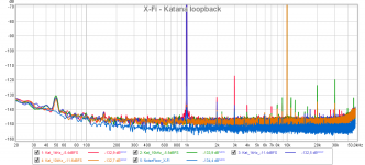
I measured the distortion of the modified Creative X-Fi using the katana as source. Here the results:
1kHz@-5.4dBFS THD(!without noise!) = 0.00027% = -111dB
1kHz@-11.4dBFS THD = 0.000097% = -120dB
10kHz@-5.5dBFS THD = 0.00023% = -112dB
10kHz@-11.6dBFS THD = 0.000099% = -120dB
When you get close to the FullScale of the ADC, the distortion rise quite sharply, so better to stay below -6dB which means the noise becomes dominant in the THD+N.
Here a screenshot and the REW file for more details
Attachments
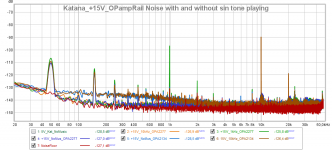
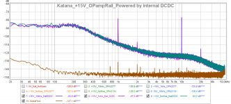
I measured the output voltage of a modified "Studer" regulator using a dynamic load, in order to get an overview of the output impedance.
I used the regulator to power the +-15V Opamp board of the Katana DAC.
Then I measured the voltage when no music was playing, and with a pure sinusoidal tone -12dB amplitude at 1kHz and 10kHz.
In the image in attachment, we can clearly see the correlation of the output voltage with the tone played by the dac.
For comparison, I also attach the same measurement of the Katana power rail power by the internal DCDC converter+internal regulator.
The "Studer" regulator is better than the katana internal regulator but it is certainly not low enough to make it negligible.
I do not know how many mOhm the output impedance could be. I do not know if it is the regulator that limits the output impedance, or the cables and contact resistances.
Attachments
@fabio,
Can you attach files of OPA2177 & OPA2134 comparison. In the chart, they are all clustered together.
Which sites did you take the measurements? Can you also take measurements @ Studer board close to feedback resistor R115.
And also how much current does Katana consume? You can measure R107 for a rough idea.
Thanks
Hello
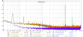
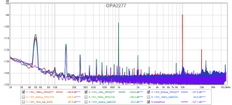
Here measurement of OPA2277 and OPA2134 split in two screenshot. I added the REW file also, to see more in detail. The voltage was measured at the katana pin. The average current should be 70mA.
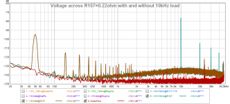
I made new measurements at R115-117-119 and across R107 as you suggested. The measure across R107 allowed me to calculate the output impedance (I think. Let me know if I am wrong). Here the results and screenshot and REW file in attachment:
R107=0.22 mOhm
R107_Idle DC = 15.6mV --> I=V/R=70mA (as from Katana spec)
Vac@R107_10kHzLoad
Voltage of 10kHz peak = -76.5dBu = 115.9uV --> 526uA
Vac@KatanaPin_10kHzLoad
Voltage of 10kHz peak = -88.7dBu = 28.45uV --> R=V/I = 54mOhm
Vac@Regulator screw Terminal_10kHzLoad
Voltage of 10kHz peak = -92.3dBu = 18.8uV --> R=V/I = 35.7mOhm
Vac@R115-117-119_10kHzLoad
Voltage of 10kHz peak = -94.2dBu = 15.1uV --> R=V/I = 28.7mOhm
Here measurement of OPA2277 and OPA2134 split in two screenshot. I added the REW file also, to see more in detail. The voltage was measured at the katana pin. The average current should be 70mA.
I made new measurements at R115-117-119 and across R107 as you suggested. The measure across R107 allowed me to calculate the output impedance (I think. Let me know if I am wrong). Here the results and screenshot and REW file in attachment:
R107=0.22 mOhm
R107_Idle DC = 15.6mV --> I=V/R=70mA (as from Katana spec)
Vac@R107_10kHzLoad
Voltage of 10kHz peak = -76.5dBu = 115.9uV --> 526uA
Vac@KatanaPin_10kHzLoad
Voltage of 10kHz peak = -88.7dBu = 28.45uV --> R=V/I = 54mOhm
Vac@Regulator screw Terminal_10kHzLoad
Voltage of 10kHz peak = -92.3dBu = 18.8uV --> R=V/I = 35.7mOhm
Vac@R115-117-119_10kHzLoad
Voltage of 10kHz peak = -94.2dBu = 15.1uV --> R=V/I = 28.7mOhm
Attachments
Not much of listening comparison yet. The OPA2277 reduces the noise compared to TL072, but I do not know if it is actually audible.
By the way, I am still having trouble to start up the Katana properly.
Now I have the regulator connected directly to the OPAmp board, bypassing the Katana regulator, but the problem is still there:
I get a little whistle at startup, then I can play music normally, but there is a lot of background noise. Setting the speaker amplifier at 50%, the noise is clearly audible without music.
But if I turn the power supply off, wait 10s second, and turn on again, the Katana starts up properly, no whistle and no noise at all.
Did you manage to start the Katana properly with the "Studer" regulator?
I am start thinking to add a relay to solve the issue, but the output impedance would increase... not good
- Home
- Amplifiers
- Power Supplies
- low noise Pre-Amp / DAC power supply MJE15034 TL072 Regulator based on STUDER 900