Please help
I made a mistake with the orientation of the power diodes. I managed to disconnect the mains as soon as I noticed that secondaries were at 8vac.
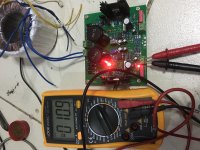
I corrected the diode orientation and the two LEDs are now on but the output is stuck at 10.9v. Already tried replacing the IC bit still 10.9v. Any tips?
I got the dual version. The other “channel” is okay
Thanks in advance
I made a mistake with the orientation of the power diodes. I managed to disconnect the mains as soon as I noticed that secondaries were at 8vac.
I corrected the diode orientation and the two LEDs are now on but the output is stuck at 10.9v. Already tried replacing the IC bit still 10.9v. Any tips?
I got the dual version. The other “channel” is okay
Thanks in advance
Attachments
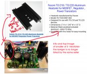
Dropping 9VAC to 5VDC at 1A, the heatsink will have to dissipate 7-8 watts of heat. It is better to use an externally mounted heatsink or the case as heatsink.you use it with the standard heatsinck? In an exclosure?
I have nothing attached to the Rpi4 exept the DAC board
So I dont think i will pull the 3A.
Still The heatsinck get very hot.
I have 9V AC input but it measure 10,4 onloaded.
I can lower the settings from the Rpi4 a bit but I dont know of it would make a lot of difference in current flow.
Chinese sellers on e-bay are very generous about the output capability of PSU they sell. It is not unusual to see a seller advertise a PSU for 45 watts output with a 15VA power transformer in the box. For reliability, I will not recommend using MJE15034 for any more than 1A output (with externally mounted heatsink). And no more than 0.3A in the default form of the Studer900 clone in an fan cooled box or no more than 0.1A in closed box.
Hello again. I hope all are well and safe and mostly sane")
My dual board kit arrived about a week ago and I have placed all the components but not started soldering yet. My transformer (30VA r-core with 2 x 9v outputs) hasn’t arrived yet but I believe it’s only a matter of days away. The wrinkle is that in the meantime I’ve bought an AURALiC Aries mini which will replace the Pi/Boss in my main system so I’m thinking I may repurpose the LPSU for that instead. It requires 16V at 1A. So, questions:
1. Is there any advantage (or even possibility) to use the dual board to drive only the Aries mini or am I better off ordering a new single board specifically for the purpose (I’d rather not separate the dual boards as I still want to do the Pi/Boss thing down the track)?
2. I’m assuming that if I can use the dual board, the transformer I have on the way will not be appropriate for a single 16V output. What should I replace it with?
Thanks in advance
Bump?
This is a bummer...Dropping 9VAC to 5VDC at 1A, the heatsink will have to dissipate 7-8 watts of heat. It is better to use an externally mounted heatsink or the case as heatsink.
Chinese sellers on e-bay are very generous about the output capability of PSU they sell. It is not unusual to see a seller advertise a PSU for 45 watts output with a 15VA power transformer in the box. For reliability, I will not recommend using MJE15034 for any more than 1A output (with externally mounted heatsink). And no more than 0.3A in the default form of the Studer900 clone in an fan cooled box or no more than 0.1A in closed box.
...the spec's of the MJE15034 said 350V..4A.I think I will need to dissipate 25W max. Maybe on average 8W.
you use it with the standard heatsinck? In an exclosure?
I have nothing attached to the Rpi4 exept the DAC board
So I dont think i will pull the 3A.
Still The heatsinck get very hot.
I have 9V AC input but it measure 10,4 onloaded.
I can lower the settings from the Rpi4 a bit but I dont know of it would make a lot of difference in current flow.
9VAC means that the voltage, after the bridge and smoothing electrolythic capacitor is 9x1.41 = 12.6VDC; the RPi requires 5VDC so 7.6VDC x 2A (being conservative) = 15W of Power(heat) that needs to be dissipated. This is why the present heatsink gets so hot...
Typical commercial grade MJE15034 has a transistor junction rating of 125°C. For reliability and stability consideration, it is better to keep the junction temperature to below 110°C. This is the core temperature inside the transistor case, not the external heatsink temperature which could be higher. Junction temperature during steady state operation depends on the overall junction to ambient thermal resistance, °C/W, of the design. The °C/W refers to the waste heat of the PSU which is the AC to DC voltage drop times current. The output power (5V at 1A etc) goes to the circuit loads and does not bother the PSU.This is a bummer...
I think I will need to dissipate 25W max. Maybe on average 8W.
I stated my recommendation for the Studer900 design "as is" in easy to understand term. It is an estimate based on many assumptions. Put a small muffin fan near the MJE15034 heatsink (computer PC CPU style) can lower the thermal resistance significantly. Using the Studer900 for application requiring 1A output is putting it at the rugged edge of its original design. It is a fun DIY adventure. Good luck.
p.s. I wrote my answer before I read CallMeMike's post. He is right on.
Last edited:
I can understand all this...but stil Im confused.
The Specs from the MJE15034 said :
4.0 AMPERES
POWER TRANSISTORS
COMPLEMENTARY SILICON
350 VOLTS, 50 WATTS
Im using it to power a Rpi4 which will draw max 3A. (in my case only used for music and have only DAC attached..so will be less).
At 3A I have around 25W to dissipate MAX I assume on average will be around 8W.
From my understanding the standard heatsinck is not sufficient.
But is a way to go to use following heatsink 2.7°C/W?
http://www.farnell.com/datasheets/1...52.1129022016.1594560217-726883113.1594560217
Or it smaller brother at 3.3°C/W
Or attach it to the case?
Or is there no way to use it about 1A?
The Farnell heat sink can work with fan cooling in a well ventilated case. Otherwise, case cooling may be better.I can understand all this...but stil Im confused.
The Specs from the MJE15034 said :
4.0 AMPERES
POWER TRANSISTORS
COMPLEMENTARY SILICON
350 VOLTS, 50 WATTS
Im using it to power a Rpi4 which will draw max 3A. (in my case only used for music and have only DAC attached..so will be less).
At 3A I have around 25W to dissipate MAX I assume on average will be around 8W.
From my understanding the standard heatsinck is not sufficient.
But is a way to go to use following heatsink 2.7°C/W?
http://www.farnell.com/datasheets/1...52.1129022016.1594560217-726883113.1594560217
Or it smaller brother at 3.3°C/W
Or attach it to the case?
Or is there no way to use it about 1A?
Hello again. I hope all are well and safe and mostly sane
My dual board kit arrived about a week ago and I have placed all the components but not started soldering yet. My transformer (30VA r-core with 2 x 9v outputs) hasn’t arrived yet but I believe it’s only a matter of days away. The wrinkle is that in the meantime I’ve bought an AURALiC Aries mini which will replace the Pi/Boss in my main system so I’m thinking I may repurpose the LPSU for that instead. It requires 16V at 1A. So, questions:
1. Is there any advantage (or even possibility) to use the dual board to drive only the Aries mini or am I better off ordering a new single board specifically for the purpose (I’d rather not separate the dual boards as I still want to do the Pi/Boss thing down the track)?
2. I’m assuming that if I can use the dual board, the transformer I have on the way will not be appropriate for a single 16V output. What should I replace it with?
Thanks in advance
If you connect the 2 x 9Vac secondaries in series you will have an 18Vac supply that you could connect to one side of the Studer900 clone board. That would allow the board to produce the 16Vdc that you require.
An 18Vac input will produce about 24Vdc at the smoothing caps so your regulator will need to lose about 8V in producing the 16V output you require. At 1 amp the heatsink will need to dissipate about 8W. You will need to make sure that your heatsinking can handle that and, if not, upgrade your solution with a larger heatsink or perhaps mount the heatsink onto the case.
With this scenario one side of your Studer900 clone board will remain unused.
Hope this helps.
Thanks, Bo
In the meantime, I’ve decided to build it as a dual rail supply as I have sourced a transformer with 2 x 12V outputs, which, as I understand it, will give me +8V on one side and -8V on the other
I don’t know if there will be any benefit over a single rail - there seems to be some disagreement over that - but I’d rather use the parts I have
Successful (so far) Raspberry Pi 4 power via modified "Studer 900" kit
I am powering a Raspberry Pi 4 running Volumio with the Studer 900 kit successfully... so far.
I post this not as a recommendation but simply sharing what is working for me. Don't try this at home. If anyone with more expertise wants to chime in with a critique or enhancement, please do so.
If you are considering trying this, I suggest getting validation from an expert or 2 first if you are not one yourself.
1. The limiting resistor value is .1 ohm, which is how the kit was supplied.
2. I modified it otherwise as per the very helpful suggestions by bbucher in this thread. ... with the exception of eliminating the diodes. which I left in place as plenty of current is available without that mod.
3. The R-Core Transformer with 2x12v secondaries is a ZeroZone purchased on eBay.
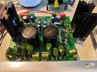
4. The 2.5" tall much larger heatsink is the perfect height to create a tight seal with the aluminum enclosure from eBay.... both of those items are no longer available from the links I purchased from but I assume you could find them with the images I attached as a reference.
5. I replaced both heatsinks...
5a. one with a 2" high heatsink that was still 30% larger than the original. This is on the side that powers a MiniSharc at 5v successfully... it barely gets warm in use.
5b. the side that powers the Raspberry Pi 4 uses a heatsink that is too large to fit on the board, so I extended the transistor legs by soldering to 18g solid copper wire. I also used copper wire to mechanically attach it to the board.
5c. With the heatsink just off the side of the board hanging on like a capsized drunk sailor to a raft, it is the perfect height to make a firm connection to the aluminum enclosure top and bottom. I drilled 2 holes in the enclosure below for its legs and "soldered" it in. When the top is screwed down, the torque required implies a pretty good seal.
5d. The original heatsinks were "hot" with voltage as the kit was supplied. So, for both, I used an insulator kit and confirmed electrical isolation with a multimeter. I used thermal compound where the transistor connects to the heat sink (via the insulator gasket) and on the bottom where it contacts the enclosure. I doubt the thermal conductivity between surfaces is ideal, but it does the job.
Used as such, the heatsink gets warm but not hot. I can keep my finger on it indefinitely.
6. I'm working up a heatsink temp monitoring system with Arduino and LM35 temperature sensors. (link) I haven't implemented it yet but would feel better with this insurance in place so it will cut off the Pi with a proper shutdown if things start to get too hot.
Unlike the eBay purchased "5V 3.5A" linear power supply, I was using for the Raspberry Pi 4 (4GB Ram) before, this one does not drop in voltage at all during startup and creates no "low voltage" warnings when I check by logging Volumio activity.
And the enhancement in sound quality is quite noticeable.
Next step - Ultracaps in parallel.
Cheers
Chris
I am powering a Raspberry Pi 4 running Volumio with the Studer 900 kit successfully... so far.
I post this not as a recommendation but simply sharing what is working for me. Don't try this at home. If anyone with more expertise wants to chime in with a critique or enhancement, please do so.
If you are considering trying this, I suggest getting validation from an expert or 2 first if you are not one yourself.
1. The limiting resistor value is .1 ohm, which is how the kit was supplied.
2. I modified it otherwise as per the very helpful suggestions by bbucher in this thread. ... with the exception of eliminating the diodes. which I left in place as plenty of current is available without that mod.
3. The R-Core Transformer with 2x12v secondaries is a ZeroZone purchased on eBay.
4. The 2.5" tall much larger heatsink is the perfect height to create a tight seal with the aluminum enclosure from eBay.... both of those items are no longer available from the links I purchased from but I assume you could find them with the images I attached as a reference.
5. I replaced both heatsinks...
5a. one with a 2" high heatsink that was still 30% larger than the original. This is on the side that powers a MiniSharc at 5v successfully... it barely gets warm in use.
5b. the side that powers the Raspberry Pi 4 uses a heatsink that is too large to fit on the board, so I extended the transistor legs by soldering to 18g solid copper wire. I also used copper wire to mechanically attach it to the board.
5c. With the heatsink just off the side of the board hanging on like a capsized drunk sailor to a raft, it is the perfect height to make a firm connection to the aluminum enclosure top and bottom. I drilled 2 holes in the enclosure below for its legs and "soldered" it in. When the top is screwed down, the torque required implies a pretty good seal.
5d. The original heatsinks were "hot" with voltage as the kit was supplied. So, for both, I used an insulator kit and confirmed electrical isolation with a multimeter. I used thermal compound where the transistor connects to the heat sink (via the insulator gasket) and on the bottom where it contacts the enclosure. I doubt the thermal conductivity between surfaces is ideal, but it does the job.
Used as such, the heatsink gets warm but not hot. I can keep my finger on it indefinitely.
6. I'm working up a heatsink temp monitoring system with Arduino and LM35 temperature sensors. (link) I haven't implemented it yet but would feel better with this insurance in place so it will cut off the Pi with a proper shutdown if things start to get too hot.
Unlike the eBay purchased "5V 3.5A" linear power supply, I was using for the Raspberry Pi 4 (4GB Ram) before, this one does not drop in voltage at all during startup and creates no "low voltage" warnings when I check by logging Volumio activity.
And the enhancement in sound quality is quite noticeable.
Next step - Ultracaps in parallel.
Cheers
Chris
Attachments
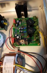

Have you consider bolting the MJE15034 to the aluminum case bottom directly to get better heatsink effect? You seem to have enough space for that in your picture.I am powering a Raspberry Pi 4 running Volumio with the Studer 900 kit successfully... so far.
I post this not as a recommendation but simply sharing what is working for me. Don't try this at home. If anyone with more expertise wants to chime in with a critique or enhancement, please do so.
If you are considering trying this, I suggest getting validation from an expert or 2 first if you are not one yourself.
4. The 2.5" tall much larger heatsink is the perfect height to create a tight seal with the aluminum enclosure from eBay.... both of those items are no longer available from the links I purchased from but I assume you could find them with the images I attached as a reference.
5. I replaced both heatsinks...
Used as such, the heatsink gets warm but not hot. I can keep my finger on it indefinitely.
6. I'm working up a heatsink temp monitoring system with Arduino and LM35 temperature sensors. (link) I haven't implemented it yet but would feel better with this insurance in place so it will cut off the Pi with a proper shutdown if things start to get too hot.
Unlike the eBay purchased "5V 3.5A" linear power supply, I was using for the Raspberry Pi 4 (4GB Ram) before, this one does not drop in voltage at all during startup and creates no "low voltage" warnings when I check by logging Volumio activity.
And the enhancement in sound quality is quite noticeable.
Next step - Ultracaps in parallel.
Cheers
Chris
Hope to see your heatsink temp monitoring system result soon. For the mean time, can you take a reading of the heatsink/case top contact point temperature with an IR thermometer?
Have you consider bolting the MJE15034 to the aluminum case bottom directly to get better heatsink effect? You seem to have enough space for that in your picture.
Hope to see your heatsink temp monitoring system result soon. For the mean time, can you take a reading of the heatsink/case top contact point temperature with an IR thermometer?
I considered it and would possibly have done so as the next step had what I did not worked so well.
I’ll loop back with the heat sink monitoring feedback via the chip+ Arduino ASAP - thanks for the encouragement. I don’t have an IR thermometer currently, though.
That larger heat sink was barely warm to the touch powering the Pi 4, so that subjective feedback gave me enough confidence to press on. That was NOT the case using the other side of the board, with its smaller (But larger than original) heat sink, to power the Pi 4. It got too hot to touch within a minute, at which point I shut things down. That size heat sink works fine powering the lower-current-needs MiniSharc, though.
Chris
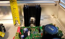
Heat sink clamped to enclosure
....I also want to emphasize that I suspect it’s largely due to the fact that the larger heat sink is the perfect size to get firmly clamped between the top and bottom of the enclosure .... and thus pass along some heat to the aluminum enclosure .... that is making it seemingly so effective at shedding heat.
As I mentioned earlier, I helped that a bit with thermal compound between the heat sink and the bottom of the enclosure. Given how often I take off the lid currently, I did not add between the hs and the top...and it doesn’t seem I need to.
Another point is that I made sure the heat sink was electrically isolated properly as well to reduce shock risks.
C
Yes, you have done the right thing. Aluminum is a very good conductor. The large heatsink passes the heat to the box effectively, then to outside air. The large heatsink by itself will not be effective at all due to the very low natural convection film coefficient from the heatsink to air inside the box which will make the heatsink to get very hot quickly.....I also want to emphasize that I suspect it’s largely due to the fact that the larger heat sink is the perfect size to get firmly clamped between the top and bottom of the enclosure .... and thus pass along some heat to the aluminum enclosure .... that is making it seemingly so effective at shedding heat.
As I mentioned earlier, I helped that a bit with thermal compound between the heat sink and the bottom of the enclosure. Given how often I take off the lid currently, I did not add between the hs and the top...and it doesn’t seem I need to.
Another point is that I made sure the heat sink was electrically isolated properly as well to reduce shock risks.
C
Making sure the heat sink to be electrically isolated properly is very important too. Congratulation to your success.
Yes, you have done the right thing. Aluminum is a very good conductor. The large heatsink passes the heat to the box effectively, then to outside air. The large heatsink by itself will not be effective at all due to the very low natural convection film coefficient from the heatsink to air inside the box which will make the heatsink to get very hot quickly.
Making sure the heat sink to be electrically isolated properly is very important too. Congratulation to your success.
Thanks for the feedback ... it was really just luck that I ended up with an enclosure and heat sink that lent themselves to making a tight fit ... I imagine both are easily found on eBay even though the original sources vaporized so wanted to pass along to others who might want to power a Raspberry Pi 4 with this - to my ears - good sounding, reasonably-priced power supply.
- Home
- Amplifiers
- Power Supplies
- low noise Pre-Amp / DAC power supply MJE15034 TL072 Regulator based on STUDER 900