
Counting on thumbs: single straight 6SN7 gives gain about 14. Used as a pair this way, about half, say 7. Gain of 7 is 17dB. Your low plate resistor may give less. So you may not get 18dB, though you could get close, with _no_ NFB applied.
I made a few changes in Spice and was able to get a good simulation using a 6080, total output noise was 160nWs, which translates ripple voltage in the micro volt region. This one is set for 300VDC.
Attachments
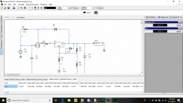
R10/C47 could cause stability problems around the LM317 -- they drop the gain precipitously near 20kHz -- consider changing R10 to 10R and C47 to 10u.
Thanks it cuts the noise floor in half!!! According to my simulations.
Is like a Maida with tube.
Yes Sir. I’m just now starting extensive listening tests, I’ve never
Heard such silence when the musics not playing!!
Also causes the regulator to be only marginally stable.Thanks it cuts the noise floor in half!!! According to my simulations.
LM317 isnt a quiet regulator by any stretch. If you must use an LM317, for lower noise hang a 10uF aluminum electrolytic off the ADJ pin.
Also causes the regulator to be only marginally stable.
LM317 isnt a quiet regulator by any stretch. If you must use an LM317, for lower noise hang a 10uF aluminum electrolytic off the ADJ pin.
Do you think the LT1084,or LT3080 would be a better choice?
The noise will be reduced by the suggestion I made - it's a usual technique with the tradeoff of somewhat reduced transient response.
LT3080 is a horse of a completely different color. PSRR at least 20dB better than LM317.
Yes it is a very good regulator, it can be implemented for high voltages
As well, I would love to find a standard Berkeley spice model, that would work
In B2!!
Yes, Art of Electronics has a design which works -- at least in LTpice. Tom was selling some HV LT3080 boards.
21st Century Maida Regulator
You can modulate the current adjust pin and get it to amplify.
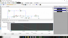
The easiest way to model any regulator using the LM317 is to do a test of impedance. In LTSpice you can click on the left axis and select phase angle. Phase angle and Q are directly related to phase margin.
If using a bode plotter with the LM317 remember that the voltage reference is tied to the positive rail.
21st Century Maida Regulator
You can modulate the current adjust pin and get it to amplify.
The easiest way to model any regulator using the LM317 is to do a test of impedance. In LTSpice you can click on the left axis and select phase angle. Phase angle and Q are directly related to phase margin.
If using a bode plotter with the LM317 remember that the voltage reference is tied to the positive rail.
Yes, Art of Electronics has a design which works -- at least in LTpice. Tom was selling some HV LT3080 boards.
21st Century Maida Regulator
You can modulate the current adjust pin and get it to amplify.
The easiest way to model any regulator using the LM317 is to do a test of impedance. In LTSpice you can click on the left axis and select phase angle. Phase angle and Q are directly related to phase margin.
If using a bode plotter with the LM317 remember that the voltage reference is tied to the positive rail.
Yes I’ve seen Tom’s designs, implementing a tube pass device wouldn’t be hard.
Analog Devices used to post generic spice models for their products
Most are designed for LTSpice, although they still post models for
Their op amps.
I'm sorry to resurrect this thread.
The conceptual circuit works using the 317, i've verified this.
Most of these circuits call for the LM317HV because some tubes require rather large negative grid voltages if you want a widely adjustable supply.
The TL783 might be a good candidate if you want to use low Mu triodes that require large negative grid voltages. The 783 also has better noise rejection then the 317.
The TL783 requires a minimum load of max 15mA to maintain regulation, as opposed to the 317's minimum load requirement of around 3mA. In the 317's case this requirement is mostly met by the divider resistors.
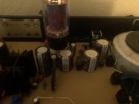
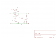
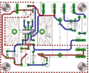
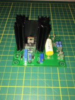
Here's my implementation, ive arrived at virtually the same circuit as Denny.
I wanted to be able to use the boards i made for experimental variable supplies, not just fixed ones. So i added a current sink to meet the TL783's minimum load requirement.
If you have an extra HV winding, you can put the output tubes in pentode mode, in which case the open loop gain will be greatly improved.
The conceptual circuit works using the 317, i've verified this.
Most of these circuits call for the LM317HV because some tubes require rather large negative grid voltages if you want a widely adjustable supply.
The TL783 might be a good candidate if you want to use low Mu triodes that require large negative grid voltages. The 783 also has better noise rejection then the 317.
The TL783 requires a minimum load of max 15mA to maintain regulation, as opposed to the 317's minimum load requirement of around 3mA. In the 317's case this requirement is mostly met by the divider resistors.
Here's my implementation, ive arrived at virtually the same circuit as Denny.
I wanted to be able to use the boards i made for experimental variable supplies, not just fixed ones. So i added a current sink to meet the TL783's minimum load requirement.
If you have an extra HV winding, you can put the output tubes in pentode mode, in which case the open loop gain will be greatly improved.
Attachments
- Status
- This old topic is closed. If you want to reopen this topic, contact a moderator using the "Report Post" button.
- Home
- Amplifiers
- Power Supplies
- Simplest possible tube regulator -- will it work?