Hello,
I'm seeking your advice and expertise for a new project that I've recently started. My objective is to design and build a very high quality, very safe, very stable 13.8v Linear DC Power Supply that can sustain up to 80 Amps at a 50% to 75% duty cycle, and 60 Amps full duty-cycle. At this stage, I've pieced together a design based on old schematics found while cruising the web that makes use of the LM723 voltage regulator. I realize there are linear regulator alternatives, but I'm using the LM723 for this build. I'm building this power supply to be rock solid and reliable. For example, I'm using a single 2N5686G to drive 10 output stage 2N5686G Series Pass Transistors. Each output transistor is capable of 50 Amps and has a breakdown voltage of 80Vdc. I'll only pull a maximum of 8 Amps per transistor. Yes, this is perhaps a bit overkill, but that's how I like it. The output current will be load-balanced using 0.047 Ohm 12.5W resistors (chassis mounted w/heat sink casings) to ensure each transistor is equally sharing the load.
Let me share a little about the build objectives and key power supply features:
I'm not as concerned with the cost to build this power supply[/U] as I am building it correctly, to spec, with rock-solid protection features as noted above. For example, the chassis alone will be approximately $550, the Transformer was $225 shipped, the pass transistors were $375 including the mounting sockets, the balancing resistors were $65, the filtering caps were $206, and the bridge was $68.
Here is a listing of critical components with their specs that I've selected and purchased already:
Challenges that I'm struggling with at this point:
I'm attaching rev4 schematics with hopes that this project may peak some interest such that you feel encouraged to share your technical expertise, and perhaps even follow me along this exciting journey. There's no doubt I have a lot to learn, and I'm open to your harsh critique, although if you throw a little humor in once in a while that would be great too! :-DD
Thanks!
Steve
I'm seeking your advice and expertise for a new project that I've recently started. My objective is to design and build a very high quality, very safe, very stable 13.8v Linear DC Power Supply that can sustain up to 80 Amps at a 50% to 75% duty cycle, and 60 Amps full duty-cycle. At this stage, I've pieced together a design based on old schematics found while cruising the web that makes use of the LM723 voltage regulator. I realize there are linear regulator alternatives, but I'm using the LM723 for this build. I'm building this power supply to be rock solid and reliable. For example, I'm using a single 2N5686G to drive 10 output stage 2N5686G Series Pass Transistors. Each output transistor is capable of 50 Amps and has a breakdown voltage of 80Vdc. I'll only pull a maximum of 8 Amps per transistor. Yes, this is perhaps a bit overkill, but that's how I like it. The output current will be load-balanced using 0.047 Ohm 12.5W resistors (chassis mounted w/heat sink casings) to ensure each transistor is equally sharing the load.
Let me share a little about the build objectives and key power supply features:
- The primary use is for my HAM Radio hobby. Granted, I do not need an 80 AMP 13.8V supply for my hobby, as I'm typically only needing up to 50 AMPS, but I wanted to challenge myself and learn at the same time. To be honest, there is a little bit of a cool-factor in building such a beast of a linear supply the right way, including applicable safety features. I currently use an Astron VS-70M that struggles to drive a VHF amplifier that I use quite often. The Astron supply is supposedly capable of 56 AMPS full duty-cycle, but trust me, it would require liquid nitrogen to keep it cool at that output level. I want to build a power supply that wouldn't even break a sweat at 60 AMPS full duty-cycle.
- Design criteria - 13.8V, 80 AMPS at up to 75% duty-cycle, soft starting, over voltage protection, current limiting, short circuit protection, remote voltage sensing and automatic active cooling fan control (with replaceable dust filters).
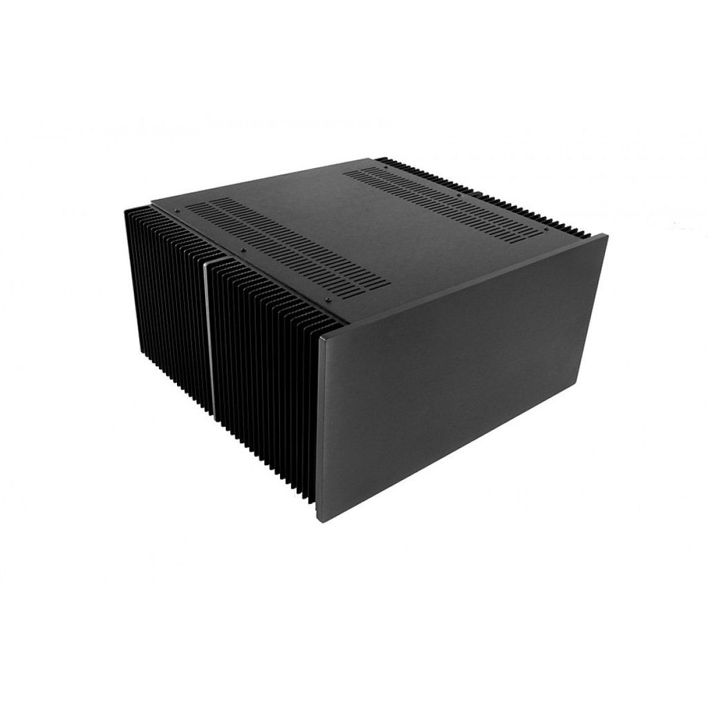
- The power supply needs to look as GREAT as it performs. I'm strongly considering using a Chassis sold by diyAUDIO that has large external fin heat sinks which fully account for both sides of the chassis. It is in a 4U size chassis and 400mm deep. It's a large chassis, yes, but the size is required for the Transformer, filter caps, etc.
I'm not as concerned with the cost to build this power supply[/U] as I am building it correctly, to spec, with rock-solid protection features as noted above. For example, the chassis alone will be approximately $550, the Transformer was $225 shipped, the pass transistors were $375 including the mounting sockets, the balancing resistors were $65, the filtering caps were $206, and the bridge was $68.
Here is a listing of critical components with their specs that I've selected and purchased already:
- AC power entry: TE Connectivity filtered module
- AC power entry fuse: 13 AMP push-button breaker (metal casing)
- Transformer: Antek 1500VA 17V (they are building this one for me, as it is not a common size)
- Bridge Rectifier: IXYS 160 AMP, 1200 V. Max surge = 2800 Amps, Vf = 1.43, power dissipation = 300W at 25C, screw mounting
- Filter Caps: Vishay 0.082F / 50V (quantity 2) for a total of 0.164F filtering
- Pass Transistors: 2N5686G (quantity 11, with one used as the Driver). 50 AMP / 80V
- Current-balancing resistors: Vishay 12.5W 1% - 0.047 Ohms
Challenges that I'm struggling with at this point:
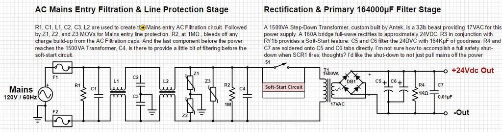
- Soft-Start - Just prior to the power transformer on the schematic, you'll see a box labeled Soft-Start Circuit. I'm leaning towards timing circuits and/or power resistors with Relay solutions. I've found one on ebay, but it's so cheap that I can't help but question the quality of components. What are your thoughts about incorporating it into my circuit? Here's a the link; Assembled soft-start w/thermal protection.
- I can't figure out what to do with the circuit when the SCR1 fires due to over-voltage scenarios. I need to add some type of crow-bar system, but I just have no idea how to design that, how to wire it up, and how to build it. Thoughts?
I'm attaching rev4 schematics with hopes that this project may peak some interest such that you feel encouraged to share your technical expertise, and perhaps even follow me along this exciting journey. There's no doubt I have a lot to learn, and I'm open to your harsh critique, although if you throw a little humor in once in a while that would be great too! :-DD
Thanks!
Steve
Last edited:
AC input has safety ground not done correctly. Always use a single fuse (never fuse neutral, possibly leaves hot live during a fault). read up on these things before going any further!
Use a separate winding to power the control and driver transistor circuits higher than the pass transistors. You will see much better efficiency, heat sinking, allowing better duty cycle ratings. Understand transformer regulation at high currents before buying a transformer, avoid much teeth gnashing and expense later. (which since you've already taken the liberty to ordering one w/o counsel, kinda expensive lessons)
Find the 'Astron Power supply repair' website and study it for a week or so , come back if you have any more questions.
You know this project is very high power and isn't forgiving for any details left unturned or lessons learned best with gradual experience. what is yours?
BTW The new hams use a good storage battery powered with a modern SMPS at 13.8VDC which lowers duty cycle unless your transmit key gets stuck. I reckon they have a recommend source for low noise ones. It's silly to have all that input AC filtering on a linear PS unless you have a unique requirement.
Last edited:
If you want it very safe, then it must withstand short circuit. 90A*20V=1800 W dissipation. You need very strong fans on every heat sinks to keep them not dangerously hot, or fold-back current limiting.
Thanks for the comments. I was beginning to wonder if there would be any on this forum. I'm curious, the current limiting in the circuit would prevent any extended 90A scenarios, and the high-voltage SCR1 w/ crow-bar protection circuit (which has just to be added to the schematic, but discussed in my post as part of the design) immediately shuts down the output. I'm confused why you think the system needs to be built to manage 1800 W dissipation levels? As I stated, 100% duty-cycle at 60A is the objective under normal use while operating in TX mode with ham radio transmitters. As designed, the internal Fan cooling offers 102CFM at the highest 190mA setting, which will provide a forced-air cooled environment internally, exiting hot air out the top panel fins. The cooling is +pressure by design, which of course requires a powerful and reliable DC Fan which costs $90. This is more protection, better heat dissipation, and more reliable equipment than the Astron 70A (which I currently use for my ham shack power supply). Have you seen how poorly that supply has been designed? If you're not familiar with it, I can tell you that it's no where near built as you're suggesting here.
This is a 13.8V / 80A supply, being designed for 50-75% duty-cycle at that max power level. As is the case with any power supply, I have zero intention of actually using it at the 'Maximum' levels, but yes I do want it built to that capability, so that I can use it at 60A reliably and safely without looking over my shoulder to see if it's smoking during use. I made that clear in my initial post, therefore your response is confusing; please clarify.
AC input has safety ground not done correctly. Always use a single fuse (never fuse neutral, possibly leaves hot live during a fault). read up on these things before going any further!
Use a separate winding to power the control and driver transistor circuits higher than the pass transistors. You will see much better efficiency, heat sinking, allowing better duty cycle ratings. Understand transformer regulation at high currents before buying a transformer, avoid much teeth gnashing and expense later. (which since you've already taken the liberty to ordering one w/o counsel, kinda expensive lessons)
Find the 'Astron Power supply repair' website and study it for a week or so , come back if you have any more questions.
You know this project is very high power and isn't forgiving for any details left unturned or lessons learned best with gradual experience. what is yours?
BTW The new hams use a good storage battery powered with a modern SMPS at 13.8VDC which lowers duty cycle unless your transmit key gets stuck. I reckon they have a recommend source for low noise ones. It's silly to have all that input AC filtering on a linear PS unless you have a unique requirement.
Thanks for responding. I've seen 2nd winding designs used as well as single winding design, and have been counselled in both directions over the past week. Are you referring to the low power factor, and suggesting the LM723 get its own power supply perhaps? If yes, I think that sounds like a great idea!
The Xantrex XFR12-100 Programmable DC Power Supply (12V / 100A) uses the same dual fuse design as the design I'm about to build. That's a very nice $1500 supply heavily regarded as a best-practices design. I'm curious to know why you strongly discourage that design, specifically?
Thanks for inviting me back if I have more questions, although what's the point, as of yet, you have not addressed the two questions / challenges that I clearly noted in my initial post. I'd like to hear your thoughts on those before I spend more time on additional questions.
Well, I'm not a career electronics and power supply engineer. If I were, I wouldn't be here asking for analysis from strangers on a diy audio forum. Although, I did make it through two years of extensive electronics and RF schools, after which diagnosed and repaired avionics gear to the circuit-level in the F-14 and S-3 aircraft for the Navy for 5 years when I was much younger. I would say I can solder with the best of them, and I do have an incredible electronics testing lab/bench in my home that would impress the socks off your feet.
You mentioned that I should study the Astron Power Supply repair site and then perhaps come back with more questions. I believe you're referring to the Welcome to Repeater Builder Dot Com site, where Astron supplies are part of the content. Yes, I enjoy having that site on my Chrome browser's favorites Bar, which it has been for at least 4yrs now If I had to guess. That site and my experience with Astron supplies are the primary reason why I've chosen to build a 'better' DC Linear.
You mentioned how silly input filtering is on a Linear. We disagree. Two things; as I've stated, this power supply is destined for Ham Shack radio room operations. Noise is of paramount concern. Noise is also why I'm building a Linear supply instead of a switcher. The simplistic design of a Linear is also why I'm building it instead of a switcher. The power input module that I'm using for this build has the filtering built into it. Line filtering never hurts, regardless of the installation specifics.
I hope you take at look at my two questions / challenges noted in my initial post with as much enthusiasm as you have with my common-side Fuse and common-mode filtering on the input.
")
Thanks for the comments. I was beginning to wonder if there would be any on this forum. I'm curious, the current limiting in the circuit would prevent any extended 90A scenarios, and the high-voltage SCR1 w/ crow-bar protection circuit (which has just to be added to the schematic, but discussed in my post as part of the design) immediately shuts down the output.
If you will really implement shut down type short circuit protection then it's OK, but I didn't find information about this. I found only a simple current limiter.
I
'm confused why you think the system needs to be built to manage 1800 W dissipation levels? As I stated, 100% duty-cycle at 60A is the objective under normal use while operating in TX mode with ham radio transmitters. As designed, the internal Fan cooling offers 102CFM at the highest 190mA setting
What type of fan can blow 102 CFM at 190 mA?
If you will really implement shut down type short circuit protection then it's OK, but I didn't find information about this. I found only a simple current limiter. What type of fan can blow 102 CFM at 190 mA?
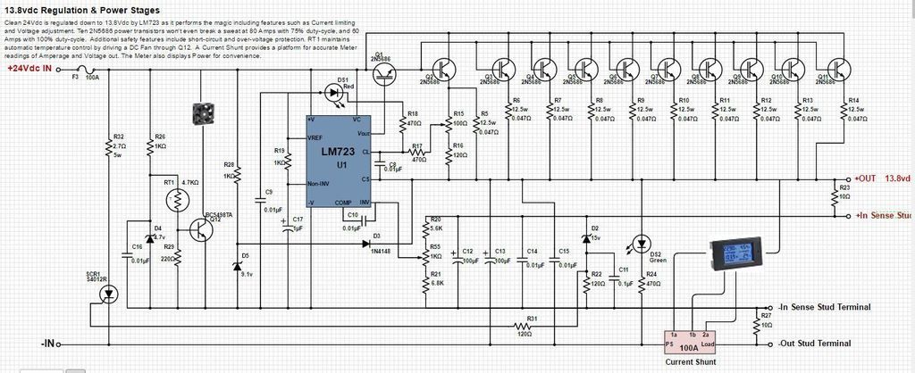
Yes, the LM723 and associated components prevent current from reaching above 80Amps. And, during a short circuit scenario on the load side, pin 10 on the LM723 (the current output drive pin) has all of its current removed by an internally biased transistor. This is one of THE best features of the LM723 and for which made it the most popular and utilized linear regulator of all time.
The DC Fan Part #: 9LB1224H101. It was made by Sanyo Denki and retails for $90 USD. It is also Sensor compatible; quite nice.
Sorry, it took me some time on mobile during travel to find every info, now I see there is fold back in the limiting under 5 V, so worst case voltage drop with max current is only about 15 V. Stil very high power. Limit current should be higher than the specified one. And 0.047ohm * 8A is less than 400 mV, so limit will be significantly higher than 80 A with these values.
I also use lm723 in my lab supply made in 1993, but with elevated supply for the IC. For fixed voltage and high current I would use MOSFETs. Or LLC SMPS.
That fan is really specified for very high CFM (at zero pressure), but it can produce low static pressure. On that tiny slots it will be damped very much. And how do you plan to force the air on the outer surface? I know, intentionally there will be not that much dissipation (however 400 W on that surface can be painfully hot without external forced cooling), but what about an accident?
Q12: I cant see the part no clearly, but some BC... will it be enough in linear operation?
of course it is, but do you know why? it allows the min. voltage Vin to be used to maintain regulation at max current, any excess is wasted as heat. (Vin-Vo)/Io = power wasted. The bias supply for the driver is typically ~5V higher than Vin ( note Astrons design tracks Vin) at a fraction of the output current. This is designed for significant power savings. The only advantage you have over Astron is that you can target the Vin more accurately b/c you know your shacks AC line voltage with better certainty than they do. A huge Variac would be useful to dial it in IF you don't have the luxury of specifying a big transformer voltage more accurately under loads. I'd do this similar to Astron, wind a dozen turns of bifilar wire on the main toroid, or you could do with an added standalone transformer. I reckon if your XFMR is able to regulate at max current your already hundreds of watts in the hole over an Astron. Youre gonna need much more metal work, fans, and perhaps w/ less robustness, if you don't take action.Thanks for responding. I've seen 2nd winding designs used as well as single winding design, and have been counselled in both directions over the past week. Are you referring to the low power factor, and suggesting the LM723 get its own power supply perhaps? If yes, I think that sounds like a great idea!
some ambitions considering Astron has been in that game for decades, they know how to do it with decent performance, fairly power efficiently, and inexpensively. If you choose to do things differently you should have reasons with either analysis and/or empirical knowledge. The schematics are available on the website, please study them closer, I can probably answer any questions. Look at your rectifier stage and then theirs. You have double the diodes, why? There is more power wasted!You mentioned that I should study the Astron Power Supply repair site and then perhaps come back with more questions. I believe you're referring to the Welcome to Repeater Builder Dot Com site, where Astron supplies are part of the content. Yes, I enjoy having that site on my Chrome browser's favorites Bar, which it has been for at least 4yrs now If I had to guess. That site and my experience with Astron supplies are the primary reason why I've chosen to build a 'better' DC Linear.
perhapsthey have 240 input then it would be ok. I've given the reason why its a bad idea for a single phase AC input, is that not making sense?The Xantrex XFR12-100 Programmable DC Power Supply (12V / 100A) uses the same dual fuse design as the design I'm about to build. That's a very nice $1500 supply heavily regarded as a best-practices design. I'm curious to know why you strongly discourage that design, specifically?
I understand the application , your pocket book not mine. BTW the filtering performance of those modules typically dives at ~1/2 rated current , and makes for worse regulation , but should be safe.You mentioned how silly input filtering is on a Linear. We disagree. Two things; as I've stated, this power supply is destined for Ham Shack radio room operations. Noise is of paramount concern. Noise is also why I'm building a Linear supply instead of a switcher. The simplistic design of a Linear is also why I'm building it instead of a switcher. The power input module that I'm using for this build has the filtering built into it. Line filtering never hurts, regardless of the installation specifics.
Last edited:
Great observation; R15 and R16 will likely need adjusting once the simulation stage begins and I get a chance to breadboard this beast. R15 is variable naturally, and as part of testing and setup, will need to be adjusted to 80Amps max while there is a load applied. I use a very large BK Precision Load device in the lab for this purpose.Sorry, it took me some time on mobile during travel to find every info, now I see there is fold back in the limiting under 5 V, so worst case voltage drop with max current is only about 15 V. Stil very high power. Limit current should be higher than the specified one. And 0.047ohm * 8A is less than 400 mV, so limit will be significantly higher than 80 A with these values.
That would defeat the challenge I've given myself to create the best linear possible based on the LM723 wouldn't it.I also use lm723 in my lab supply made in 1993, but with elevated supply for the IC. For fixed voltage and high current I would use MOSFETs. Or LLC SMPS.
102 CFM at a static pressure of 62Pa is quite good for the chassis selected. If I'm missing a piece of the equation please educate me, because the Fan must be sufficient for this chassis specifically. Keep in mind that one must consider environmental factors while system engineering. In this case, there's a slight trade-off for static pressure vs. dBA. Meaning, this supply sits very near the working bench location for our Ham Radio operations. I found very little options, at any price, that fit the design criteria better than the fan specified here. If there is one I want to know about it, thanks man.That fan is really specified for very high CFM (at zero pressure), but it can produce low static pressure. On that tiny slots it will be damped very much. And how do you plan to force the air on the outer surface? I know, intentionally there will be not that much dissipation (however 400 W on that surface can be painfully hot without external forced cooling), but what about an accident?
Sorry for the small schematic size; Q12 is BC5498TA. I'm not satisfied yet that it will be sufficient, I still need to put it on the protoboard to validate.Q12: I cant see the part no clearly, but some BC... will it be enough in linear operation?
I thoroughly appreciate your time, questions, and suggestions. It is this type of dialog that I was desperately seeking.
I like the idea of a 2nd winding for the reasons you've stated....it allows the min. voltage Vin to be used to maintain regulation at max current, any excess is wasted as heat. (Vin-Vo)/Io = power wasted. I'd do this similar to Astron, wind a dozen turns of bifilar wire on the main toroid, or you could do with an added standalone transformer.
We disagree on this point. The fact that they've been making them for decades does not translate into them being well made. They are made cheaply, and have never performed to the specs in my experience. In many cases, they fail prematurely simply due to the fact that they have ****-poor quality control (solder joints specifically). They 'famously' use lousy rectification designs. I know, I repair and upgrade them often. I can't think of a single manufacture of DC Linear supplies that is more dangerous to work on than an Astron.some ambitions considering Astron has been in that game for decades, they know how to do it with decent performance, fairly power efficiently, and inexpensively.
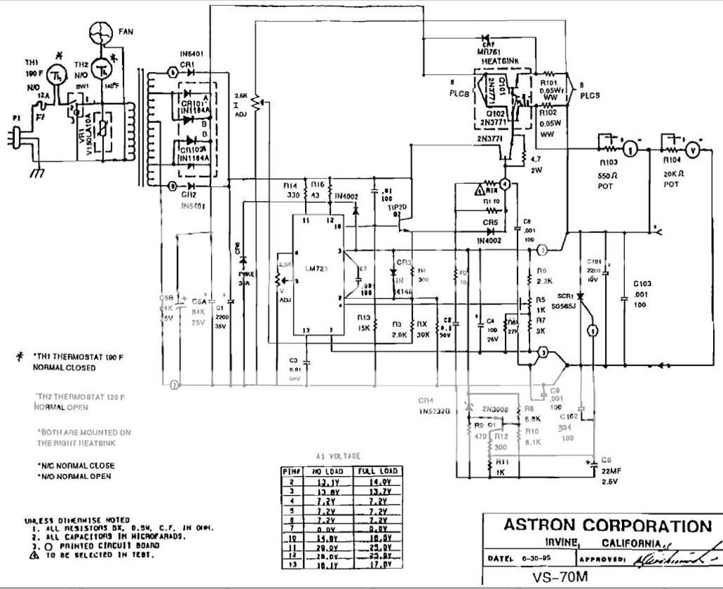
I prefer full-wave rectification. They also commonly use a parallel bridge design in their larger supplies. For example, there are 4 diodes chassis mounted to the rear panel on the VS-70M, paralleled. Is it possible you're looking at an older 1996 Astron schematic? They often make changes without updating the schematics...they are famous for doing so.Look at their rectifier stage and then yours. You have double the diodes, why? There is more power wasted.
Of course it's my pocket book, not yours. If you read my post, you would see where I specifically stated that price is not a concern for this build. If I used a cheap power input filtered module, you would be correct. But I'm not building a cheap power supply.I understand the application , your pocket book not mine. BTW the filtering performance of those modules typically dives at ~1/2 rated current , and makes for worse regulation , but should be safe.
oops correction for power wasted on pass devices (Vin-Vo)*Io there are more losses in the emitter ballasts as well. these high current designs are not trivial by any means.
Should I drop lower than .047Ω for the current-balance resistors? I think you're saying that if I did change those balance resistors to something lower, it would improve the emitter losses significantly (enough to measure a constructive change in the Power Factor perhaps?
Should I drop lower than .047Ω for the current-balance resistors? I think you're saying that if I did change those balance resistors to something lower, it would improve the emitter losses significantly (enough to measure a constructive change in the Power Factor perhaps?
I wouldn't. they've probably gone too low, unless youve matched all pass devices and are perfectly thermally tracked.
do the math for your devices. There are better ways to save power this place has more risks.
'power one' and Astec are better designs look out for their stuff.
Last edited:
Crowbars are designed to latch and blow the mains fuse , simple & effective. Never count on current limit in these cases, the most important thing is make sure they short out the secondary with super low ohms and don't sit there and cook. In most cases a single pass transistor / rectifier device has shorted before firing. Keep this in mind when sizing wire to any paralleled device.
Last edited:
I wouldn't. they've probably gone too low, unless youve matched all pass devices and are perfectly thermally tracked.
do the math for your devices.
'power one' and Astec are better designs look out for their stuff.
I'll see if I can find a schematic, but I wonder if they're using the LM723.... as that's a requirement for this build.
Here's a schematic of the VS-70M. I could be reading it wrong, but I see two diodes per cycle in the rectifier. Same as mine, no?
'power one' and Astec are better designs look out for their stuff.
Hmmm, Power One was bought out Bell Power Solutions (or something like that) but the products are sold at Mouser. The largest one available at Mouser is their $715 switching supply designed for Servers, etc. And interestingly, they use a very basic and IMO sub-standard inrush topology of an NTC. At least they very specifically state in the data sheet that the user should not plugin / unplug too often in a short period, as it would easily defeat the entire inrush protection. Granted, a Server or Network power supply is unlikely to be unplugged and immediately plugged back in, but still... this is a poor design IMO. I certainly would never rely upon just an NTC as the full extent of a soft-start (inrush protection) circuit.
different topology, they use a center tapHere's a schematic of the VS-70M. I could be reading it wrong, but I see two diodes per cycle in the rectifier. Same as mine, no?
If I remember, they typically use parallel devices in 50-100A bridge packs, one pack per side.
Last edited:
Crowbars are designed to latch and blow the mains fuse , simple & effective. Never count on current limit in these cases, the most important thing is make sure they short out the secondary with super low ohms and don't sit there and cook. In most cases a single pass transistor / rectifier device has shorted before firing. Keep this in mind when sizing wire to any paralleled device.
Good points. In regards to the crowbar and wire size on the output, Astron does a good job.
- Status
- This old topic is closed. If you want to reopen this topic, contact a moderator using the "Report Post" button.
- Home
- Amplifiers
- Power Supplies
- 13.8V 80A Linear PS circuit design analysis for Ham Radio Use