If low ambient noise is the goal, and a linear supply is the way you want to go (and not an SMPS) then perhaps a way to consider doing it, and assuming that size is not the issue, is to go "brute force". That would be a ~1kva transformer core to start, run off 240vac, not 120vac. Now you have the requisite current available. Next you need to filter and control voltage.
As I've stated, yes a linear is the design criteria, at 120Vac/60Hz. Unfortunately, that does mean the transformer is a monster. In this case, 1500VAC at approximately 32lbs and 8.2" in diameter. It does require a significant inrush strategy.
I love the ch'ching!
")
Really? 2M at a kW?? Waffor??
Are you buying or building?
IF you are building, then separate power supplies and a combiner...
Well you have my recommendations, low Vdrop for cap multipliers or Vregs, 240v mains, and big *** iron. Looks like you have the big *** iron, so just switch to a choke input filter...
... with the 17vac secondary you'll be getting 24vdc and dropping 1/2 of your voltage into raw heat. Kinda pointless with an ample bit of iron... since you already chose to get big caps, I'm puzzled. With voltage regulation the need for big caps is not there.
Soft start, a resistor of ample wattage (big) and a relay to bypass. It ought to be chosen to set your max inrush current < 50% of the breaker current. Even 25% is fine... just enough to get things up and running... In this size, maybe around 8 ohms or so is likely to work out right. Circuit to control that.
Again the benefit of sizing the iron's secondary so that the rectified and filtered DC is closer to the target voltage is that you do not need OVP if you do it right...
Also it is possible to use multiple transformers in parallel rather than one huge monster core.
_-_-bear
As I've stated, yes a linear is the design criteria, at 120Vac/60Hz. Unfortunately, that does mean the transformer is a monster. In this case, 1500VAC at approximately 32lbs and 8.2" in diameter. It does require a significant inrush strategy.
I love the ch'ching!
See, your design is upside down here
The idea behind the higher voltage that is regulated down is to use iron that is lower in amperage at a higher voltage... you've got a transformer that is rated OVER your actual current needs, and still you want to regulate it down?
Why?
The inrush strategy is to just limit the initial current - that's a big power resistor for a number of seconds... then jump it out with a relay that his a number of large contacts in parallel. Do NOT try to turn this thing on with a "switch". You really need and want another relay/contactor for this job. Switch contacts will likely blow apart.
_-_-bear
PS. hope you have a dedicated 120vac line for this? If you own the place, then 240vac is required, hope you ordered DUAL PRIMARIES??
I'm not sure what you're reading Bear. No one said that the 2M amplifiers I use require a kilowatt of power. You asked why I want big power, I said I use big amplifiers, but that doesn't mean I'm expecting to 'MAX OUT' this power supply, as that would make me pretty darn foolish. This thread is for circuit analysis, not why I need it. It's not for people to convince me to build or buy a switching supply instead of a linear. I made all of that clear in my intro. I'm not going to build it for 240Vac Mains, as it needs to be able to run on standard household power in the United States....120Vac, period.... end of story. If you're interested in looking at the design presented and offering insight to where I've got errors, etc, by all means please do, because that's why I've posted here, it's what I've asked for in my intro.Really? 2M at a kW?? Waffor?? Well you have my recommendations, low Vdrop for cap multipliers or Vregs, 240v mains, and big *** iron.
... with the 17vac secondary you'll be getting 24vdc and dropping 1/2 of your voltage into raw heat. Kinda pointless with an ample bit of iron... since you already chose to get big caps, I'm puzzled. With voltage regulation the need for big caps is not there.
I can't help with that perception there Bear. If you feel that a regulated linear does not require large filtering caps, then I'm not going to waste my time convincing you otherwise.
However, I will share with you that with high current loads, the transformer will experience a significant lag/droop, and it's important to keep the core from over-saturating. It sounds like you feel the rectified 24Vdc is stable even with a heavy load, and without large caps; you might want to read a few articles or open up a few linear power supplies and take measurements yourself. The reason the transformer is spec'd at 17Vac is to provide the required buffer to account for the unavoidable voltage droop characteristic of transformers. Its all part of the power factor of linear design.
Simple... power factor and voltage droop when using transformers.See, your design is upside down here
The idea behind the higher voltage that is regulated down is to use iron that is lower in amperage at a higher voltage... you've got a transformer that is rated OVER your actual current needs, and still you want to regulate it down?
Why?
You are familiar with Astron, yes? I assume so because you mentioned that you're a ham radio operator. I also assume that you're at least a General Class license holder or higher. In which case, you would know that the switch must be rated for design specification, and, that it typically resides in the circuit in or behind the inrush protection stage. If you would look at my schematic before you type some of these comments, many of your assumptions are clarified and/or answered already. Switch selection is likely the easiest part of the design.[/quote]Do NOT try to turn this thing on with a "switch". You really need and want another relay/contactor for this job. Switch contacts will likely blow apart.
Ok Bear, first off, 240Vac is not required for this build. I realize you're probably only trying to help, but you clearly have not read through the thread nor my intro. Astron has been building and selling 50 and 70 amp linear supplies for decades and I've yet to see them require a dedicated 120Vac line much less a 240Vac line in their documentation. Nor in my 18yrs of being an active ham radio operator have I ever popped breaker using one. I happen to have a dedicated 20A service outlet for this power supply. It will replace an Astron VS-70M... the junk box that it is.PS. hope you have a dedicated 120vac line for this? If you own the place, then 240vac is required, hope you ordered DUAL PRIMARIES??
Great point; thanks I'll make the change to R15 right away.
I'm not sure you got it. Changing value doesn't help. It is a divider. It can not make voltage higher than the voltage on the 0.047 ohm. For this purpose you have to add voltage. (Or change 0.047 to higher.)
You also asked about why I've chosen the cooling Fan specifically.
I did not.
Because it is capable of 2.9 cubit meters of air flow, with a static coefficient of 67Pa and 102 CFM. Given those operating characteristics, and that the chassis (empty) has a volume of .02 cubic meters.
I don't see any logic here. These are just the listing of the properties of the parts, without mentioning any of the requirements originated from the design details.
Internal cooling will be the least of my concerns for this build.
Because...?
Additionally, the reason the internal Fan is a viable cooling option is because 100% of the left and right panels of the chassis are the finned heat sinks. So the airflow will be in direct contact with the massive cooling heat sinks 100% of the time during operation.
100 % of the time, but how many % of surface of the heat sink, at what velocity? Maybe 15 % and unpredictable but surely not enough velocity. The fins will see next to nothing from the air flow inside.
Additionally, all of the pass transistors will be directly mounted to the heat sinks via aluminum brackets which place them directly underneath the vent slots in the top of the chassis, thereby creating a direct forced-air cooling environment.
This part will be forced air, but how much surface will be here? "Directly" and "via brackets" are contradictional terms. Directly means nothing between them. And if you place something between them, then it adds thermal resistance. You have to calculate these (and many other) quantities to check if operating temperature doesn't exceed safe operating area. Did you calculate any thermal modell?
I'm not aware of any commercially available linear supply with these specifications that has better cooling design than this. And certainly not at 39dBA.
A cooling design can be described by at least an overall thermal resistance. Do you have any estimation for this parameter? Simply saying it's good is not enough.
For the surface temperature without external fan I guess 0.15 Kelvin/Watt (your task is to search for exact data or measure it), what is very good, but still at 30 Celsius ambient temperature and 400 W dissipation it means 90 Celsius surface temperature and much higher junction temp for transistors. And this is not worst case, only typical condition. To keep is safe you must keep heat sink temp under 50...60 Celsius, or make touching them impossible. This requires external fans, and/or much lower dissipation.
I had a typo, the correct part number is BC549BTA. The Pc is 500mW.
It will operate in linear mode. Calculate worst case dissipation! It's definitely higher than 500 mW.
I'm using Tina to simulate the design, but it's frustrating because I can't find a viable LM723 (or ua723) Spice model. With my limited knowledge of how to manipulate simulation model characteristics in software, this is severely limiting my ability to properly simulate this design.
LM723 is a very simple circuit, and internal schematic is specified satisfactorily. You can build it from basic element. But simulators can't substitute knowledge of rules of electrotechnics.
For example answering to the question of dissipation saying "It's a 13.8v supply, so at 60A that's likely going to be close to 828 watts. Adding in the estimated power factor loss of approximately 1.4, that bring us to about 1160 watts" is a nonsense. There's no such thing as power factor loss. And not clear what dissipation do you refer to. Of the load? Why would it be a question? PSU? Than the answer is totally wrong. Dissipation of a 2 port device can be calculated by
subtracting output power from input power. In this case input power is not known, so an other aproach must be followed, based on the schematics. It is basically a series network, the dominant dissipation sources are the transistors and emitter resistors. Power on them can be calculated by the current on them multiplied by the voltage accross them. Input voltage is about 20 V averaged under load (18 V min 22 V max), output voltage is 13.8 V, so Pd=7.2V*60A=432W. You must add diode loss of 2.4V*60A=144W, and transformer loss, about 100W.
Your welcome! Its an interesting project, however I see many things to optimize differently.Thanks again for your time and especially for catching my math error for R15.
This is an aluminum bracket mock-up, demonstrating the approach for mounting the the TO-3 packages inside the chassis. The air vents I referred to are cut into slots on the top panel by the chassis manufacturer, directly above the mounting bracket locations you see in the photo, which creates a path for the forced air. The forced air contacts the side panels (heat sinks) and pass transistors. The Fan provides cool air swirling around inside doing a good job of dissipation before exiting the top panel slots. That's all the engineering that I'm willing to do with regard to thermal characterization at this point in the prototyping stage. If during testing, when real measurements are taken, and if it is found that there is not enough cool air dwell time internally or that the velocity is not sufficient, I'll order a different fan. Pyramid and Astron linear supplies have no where near the cooling capability of this design. So for the moment, that's good enough to start with.
My bigger concern is the circuit. I've contacted a professional engineer and am waiting to receive a quote for him to review and resolve component math issues. I think it's pretty close now, but there are holes in the math. You pointed one out already. Additionally, I'd like to have a separate +V for the regulation circuit. So, changes are being made.

My bigger concern is the circuit. I've contacted a professional engineer and am waiting to receive a quote for him to review and resolve component math issues. I think it's pretty close now, but there are holes in the math. You pointed one out already. Additionally, I'd like to have a separate +V for the regulation circuit. So, changes are being made.
This is very far from ideal thermal coupling, especially if you add insulator. And this has an insignificant surface, worth almost nothing.
I saw the cuts, but they will not cool anything, the only good thing about them is not completely disable the air flow.
Your transistors will be very hot. This is the best time to redesign. Later you will have to work very much.
I saw the cuts, but they will not cool anything, the only good thing about them is not completely disable the air flow.
Your transistors will be very hot. This is the best time to redesign. Later you will have to work very much.
For example answering to the question of dissipation saying "It's a 13.8v supply, so at 60A that's likely going to be close to 828 watts. Adding in the estimated power factor loss of approximately 1.4, that bring us to about 1160 watts" is a nonsense.
60A x 20V = 1200 watts. My estimate of 1160 watts was close enough. You're getting a little bit too comfortable with the condescension; borderline insulting. Look, I get it... you're trying to 'teach me a lesson' because clearly I'm not an electrical engineer. Does berating me make you feel good about yourself? The chassis heat sink specification = 38 C°/W. That's a great starting place for this build. Sure, I'll have some level of decreased heat sink efficiency due to the mounting solution for the TO-3 packaged devices, but with the selected Fan and chassis design, I still feel confident it's 'good enough' to proceed with building a prototype and getting real-world test results. The system design must also be easy to troubleshoot and repair. Many industrial designs place much less emphasis on that criteria, because they are building to a price point. They have to calculate the very smallest of details, in order to develop a BOM at the lowest possible cost (...lowest quality) to barely get by with a product that will last long enough to surpass the warranty period.
Good day Sir. I think it's safe to say that this thread has run its course, at least from my perspective.
An attack on your design at review time is not an attack against you personally esp. since you offered zero technical defense to back it up. no one is beating on YOU.
Throwing money at a poorer design is better than a cheap product that works albeit poorly at higher than rated powers. righty oh
If you cant understand why a product is bad how can you possibly know when one better? your response "when you can repair it much easier" ..sorry nope.
since you have an Astron, instead of throwing it away why don't you test and analyze it so you can identify problems that your design addresses? we all could learn from the data, that way we'd be working together to improve your design.
Last edited:
FJHookak, it appears to me that you are the polar opposite of ham radio people. They generally pride themselves in getting the electronics right and spending the least amount of money possible making their projects. Like getting a cheap aluminum sheet, pounding out there own chassis and buying surplus components. I think you just want a project you can assemble and for it to look pretty and do not care about the technical details.
It does not seem to me that you understood most of the things the others have said. I will recap things for you as simply as i can.
Post 1
"AC power entry: TE Connectivity filtered module."
Waste of time and money. If it was needed the internet would be flooded with Astron power supply mods with an input filter.
"Transformer: Antek 1500VA 17V (they are building this one for me, as it is not a common size)"
Throw it out. Get the right transformer. With a single winding going in to a full wave bridge your secondary ac current is 1.8 x the DC current. 80A x 1.8 = 144A. The losses are 1.4vdc two diode drops x 144A = 202W for the bridge.
With two winding's and a center tap only two diodes are needed. your secondary ac current is 1.2 x the DC current. 80A x 1.2 = 96A. The losses are .7vdc x 96A = 67W per diode = 134W.
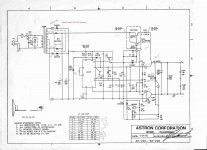
Look at the Astron schematic (see my red text on transformer). There is a center tap and two outer winding's. The first winding is 17vac from the center tap and after that winding there is a 22vac winding. You will need a volt or two more say 23 or 24 vac as i will explain later.
"Bridge Rectifier: IXYS 160 AMP, 1200 V. Max surge = 2800 Amps, Vf = 1.43, power dissipation = 300W at 25C, screw mounting"
No need for this part, get two diodes.
"Filter Caps: Vishay 0.082F / 50V (quantity 2) for a total of 0.164F filtering."
Your power supply
V = dt I/C
.00833 S 80A/.164F = 4V pp ripple
Astron
V = dt I/C
.00833 S 35A/.064F = 4.6V pp ripple
This is about the only place your money would have made a difference and you ended up about the same as the Astron.
"Pass Transistors: 2N5686G (quantity 11, with one used as the Driver). 50 AMP / 80V"
Good transistors.
"Current-balancing resistors: Vishay 12.5W 1% - 0.047 Ohms."
Good resistor wattage, wrong value. The Cs input on the LM723 needs about .7 volts to function. .7 VDC / 8A = 0.0875 ohms. 8A x .7 VDC = 5.6 W.
The 8A is assuming 10 transistors and we already discovered that 10 transistors does not divide out to 4 heat sinks. Not that it matters because as you have been told several times your heat sink scheme will not work.
My opinion, throw the case out and start over. The case is completely wrong for what you want to do. It was made for a stereo amplifier, one amp on each side of the case and separate heat sinks for each amp. How are you going to use this case? Are you going to run wires from both sides to your circuit board. If the wires are dressed out neatly along the walls then you will have 1 to 2 feet of wiring per transistor! Will that inductance effect operation? Not to mention just a sloppy build. Find a case with a big back panel all heat sink and mount the transistors properly. You will need a machine shop to mill out the heat sink, good thing you have lots of money. While you are at it have the machine shop put holes for aluminum hex extensions on the heat sink and mount a plexiglass panel 4 or 5 inches from the heat sink. Then put 2 or 3 muffin fans on the plexy blowing on the heat sink fins. Now you will have a real piece of equipment.
Back to the 23 VAC winding's. The reason they are used is to raise the LM723 output voltage to the point were it can turn the power transistors on. The LM723 is referenced to 24 VDC gnd. For it to turn on the transistor it has to be greater voltage than all of this. The output of the LM723 is 3 volts less than the input. The output of the LM723 has to go through 3 diode drops ( one darlington driver and the power transistor) .7V x 3 = 2.1V plus 3 volts = 5.1 volts DC you are short of to turn on the transistor. This is why you need 23 VAC minimum for aux winding. 23 VAC x 1.414 = 32.5 VDC - diode drop .7 VDC = 31.8 VDC - 24vdc = 7.8 VDC. Now you have 2.7 volts to spare and some room for the darlington base resistor to drop some voltage.
OK, what about this darlington i keep talking about. Your existing driver will burn the LM723 up the first time you try to use it. Ten transistors Min hFE 15. 8A each transistor / Min hFE 15 = .533A minimum base current. .533A x 10 = 5.33A minimum driver current / your current transistor choice 15 hfE min = 355 mA from a LM723 rated at 150 mA max. The 411 on the internet says this chip likes to burn up at 150 mA. I did a quick check on one Astron schematic and found they run 100 mA. So you should not exceed this either. So 5.33A minimum driver current / .1 A max from LM723 = You need min hfE of 54. I did not see a regular power transistor with a hfE min above 15. The darlington takes current to drive also, but i am just going to bump the 5.33A to 6A and call it even. I think the worst case voltage drop across the darlington would be the difference of the 2 power supply's, 7.8 VDC. So 7.8 VDC x 6A = 47 watts dissipation. This one looks OK, DigiKey MJ11012GOS-ND, min hfE 200. Your LM723 will only have to supply 6A drive / 200 min hfE = 30 mA.
Back to the transformer when you use a center tap rectifier you have 2 winding's supplying the current so each winding is rated for 1/2 the current.
The main 17 volt has to supply 96 A AC for continuous operation, i am not sure how to de-rate for lower duty cycles. 96A / 2 = 48A per winding.
The 23 VAC winding's has to supply 6A DC min so 6A x 1.2 = 7.2A AC from transformer so call it 4A per winding for a total of 8A.
The soft start. I looked at the one you picked out. It appears to me that
the power dropping resistor is on board the soft start circuit board. I think your transformer would blow it away.
As for crowbar, i did a google search and there is a wealth of information
on building them.
Axotron
Well hopefully others will look at my work and find any mistakes and add a few things of there own and get you going. Give people a couple of days to respond.
73
It does not seem to me that you understood most of the things the others have said. I will recap things for you as simply as i can.
Post 1
"AC power entry: TE Connectivity filtered module."
Waste of time and money. If it was needed the internet would be flooded with Astron power supply mods with an input filter.
"Transformer: Antek 1500VA 17V (they are building this one for me, as it is not a common size)"
Throw it out. Get the right transformer. With a single winding going in to a full wave bridge your secondary ac current is 1.8 x the DC current. 80A x 1.8 = 144A. The losses are 1.4vdc two diode drops x 144A = 202W for the bridge.
With two winding's and a center tap only two diodes are needed. your secondary ac current is 1.2 x the DC current. 80A x 1.2 = 96A. The losses are .7vdc x 96A = 67W per diode = 134W.
Look at the Astron schematic (see my red text on transformer). There is a center tap and two outer winding's. The first winding is 17vac from the center tap and after that winding there is a 22vac winding. You will need a volt or two more say 23 or 24 vac as i will explain later.
"Bridge Rectifier: IXYS 160 AMP, 1200 V. Max surge = 2800 Amps, Vf = 1.43, power dissipation = 300W at 25C, screw mounting"
No need for this part, get two diodes.
"Filter Caps: Vishay 0.082F / 50V (quantity 2) for a total of 0.164F filtering."
Your power supply
V = dt I/C
.00833 S 80A/.164F = 4V pp ripple
Astron
V = dt I/C
.00833 S 35A/.064F = 4.6V pp ripple
This is about the only place your money would have made a difference and you ended up about the same as the Astron.
"Pass Transistors: 2N5686G (quantity 11, with one used as the Driver). 50 AMP / 80V"
Good transistors.
"Current-balancing resistors: Vishay 12.5W 1% - 0.047 Ohms."
Good resistor wattage, wrong value. The Cs input on the LM723 needs about .7 volts to function. .7 VDC / 8A = 0.0875 ohms. 8A x .7 VDC = 5.6 W.
The 8A is assuming 10 transistors and we already discovered that 10 transistors does not divide out to 4 heat sinks. Not that it matters because as you have been told several times your heat sink scheme will not work.
My opinion, throw the case out and start over. The case is completely wrong for what you want to do. It was made for a stereo amplifier, one amp on each side of the case and separate heat sinks for each amp. How are you going to use this case? Are you going to run wires from both sides to your circuit board. If the wires are dressed out neatly along the walls then you will have 1 to 2 feet of wiring per transistor! Will that inductance effect operation? Not to mention just a sloppy build. Find a case with a big back panel all heat sink and mount the transistors properly. You will need a machine shop to mill out the heat sink, good thing you have lots of money. While you are at it have the machine shop put holes for aluminum hex extensions on the heat sink and mount a plexiglass panel 4 or 5 inches from the heat sink. Then put 2 or 3 muffin fans on the plexy blowing on the heat sink fins. Now you will have a real piece of equipment.
Back to the 23 VAC winding's. The reason they are used is to raise the LM723 output voltage to the point were it can turn the power transistors on. The LM723 is referenced to 24 VDC gnd. For it to turn on the transistor it has to be greater voltage than all of this. The output of the LM723 is 3 volts less than the input. The output of the LM723 has to go through 3 diode drops ( one darlington driver and the power transistor) .7V x 3 = 2.1V plus 3 volts = 5.1 volts DC you are short of to turn on the transistor. This is why you need 23 VAC minimum for aux winding. 23 VAC x 1.414 = 32.5 VDC - diode drop .7 VDC = 31.8 VDC - 24vdc = 7.8 VDC. Now you have 2.7 volts to spare and some room for the darlington base resistor to drop some voltage.
OK, what about this darlington i keep talking about. Your existing driver will burn the LM723 up the first time you try to use it. Ten transistors Min hFE 15. 8A each transistor / Min hFE 15 = .533A minimum base current. .533A x 10 = 5.33A minimum driver current / your current transistor choice 15 hfE min = 355 mA from a LM723 rated at 150 mA max. The 411 on the internet says this chip likes to burn up at 150 mA. I did a quick check on one Astron schematic and found they run 100 mA. So you should not exceed this either. So 5.33A minimum driver current / .1 A max from LM723 = You need min hfE of 54. I did not see a regular power transistor with a hfE min above 15. The darlington takes current to drive also, but i am just going to bump the 5.33A to 6A and call it even. I think the worst case voltage drop across the darlington would be the difference of the 2 power supply's, 7.8 VDC. So 7.8 VDC x 6A = 47 watts dissipation. This one looks OK, DigiKey MJ11012GOS-ND, min hfE 200. Your LM723 will only have to supply 6A drive / 200 min hfE = 30 mA.
Back to the transformer when you use a center tap rectifier you have 2 winding's supplying the current so each winding is rated for 1/2 the current.
The main 17 volt has to supply 96 A AC for continuous operation, i am not sure how to de-rate for lower duty cycles. 96A / 2 = 48A per winding.
The 23 VAC winding's has to supply 6A DC min so 6A x 1.2 = 7.2A AC from transformer so call it 4A per winding for a total of 8A.
The soft start. I looked at the one you picked out. It appears to me that
the power dropping resistor is on board the soft start circuit board. I think your transformer would blow it away.
As for crowbar, i did a google search and there is a wealth of information
on building them.
Axotron
Well hopefully others will look at my work and find any mistakes and add a few things of there own and get you going. Give people a couple of days to respond.
73
I will help you with your math. 2 to3 transistors x 4 heat sinks = 8 transistors not 10.
If you need any other help let me know.
Was this meant as a joke, to lighten the mood of the thread, so to speak perhaps? Surely you didn't mean to suggest that 3x4=10 did you? There are 11 of those transistors needed, there are two easy ways to split them across the 4 panels. This, is likely the easiest math of the build wouldn't you say?
hi Powerbob it's worse than you figured
the centertap transformer each 1/2 winding has to supply the full voltage minus only one diode drop. The other winding supports the opposite half cycle. The typical current crest factor is reduced to 1.2 from increased copper losses. A good custom XFMR will devote more secondary copper bringing 1.2 back up closer to ~1.5. Also a good rectifier will be closer to 1.1V drop not 0.7V.
The full bridge (single winding) there are a full 2 diodes drops for each half cycle, use normal crest factors.
this is a good tutorial Linear Power Supply Design
your drawing> use the 70A Astron in the thread not the RS20A to compare.
the big problem is that naive users assume 70A model is seventy amps output\
did Astron increase copper in their XFMR? nope because that would mean the EI core would grow to next size up.
Last edited:
FJHookak, it appears to me that you are the polar opposite of ham radio people. They generally pride themselves in getting the electronics right and spending the least amount of money possible making their projects. Like getting a cheap aluminum sheet, pounding out there own chassis and buying surplus components.
You haven't been around them as often as I have perhaps? Else you would know that an alarmingly high % of Ham operators are famously cheap bastards, relegated to home-built ugly looking junk for the cheapest price possible because they are typically retired without money to spend, or, they are lifelong bargain hunters and refuse to buy great equipment. I'd say that's part of the very fabric that has characterized Ham operators for decades. So, no I'm not that type of Ham operator. I'm not retired and I chose not to spend the time it would take to become an engineer. It's a fun hobby for me, and it's fun learning how to select the right transformer for example. That's why I came to this site. It sounds like you've read through the thread; 90% of the feedback I received were questions and challenges for me to 'prove' why I chose the components. If I could do that I wouldn't have posted here for guidance.
For example, if I could mathematically prove why I chose the cooling Fan specification on paper, I wouldn't need or want to come to this mad house seeking advice. Common sense tells me, based on the dozens of Astrons that have been on my workbench, that as long as my cooling was better than any I've come across, that's a good start, and it could always, always be revisited down the road. Did you notice that the gentleman who wanted to berate me over the cooling, also chose NOT to share mathematically why he felt is was so inadequate.
Something that I can pull together without needing to become a professional engineer over the next 4 months would be great, you betcha'. Is there an issue with that? I care enough to have contacted a professional engineer to perform a deep-dive analysis so that I can get the math right. Who wants an unsafe or unreliable supply? I've seen many, many home-built supplies that I wouldn't touch. That's not what this supply will be... it's will be done correctly, and where possible, more than adequately.I think you just want a project you can assemble and for it to look pretty and do not care about the technical details.
Post 1
"AC power entry: TE Connectivity filtered module." Waste of time and money. If it was needed the internet would be flooded with Astron power supply mods with an input filter.
In my experience, to most Ham operators buying anything new is a waste of time and money. I needed an entry plug; who gives a rat's behind if I chose one with a filter or not? However, if you can mathematically demonstrate how that module degrades the performance of this power supply project in any way, I'll remove it from the BOM with enthusiasm.
With two winding's and a center tap only two diodes are needed. your secondary ac current is 1.2 x the DC current. 80A x 1.2 = 96A. The losses are .7vdc x 96A = 67W per diode = 134W.
Take a look at the larger Astron supplies; VS-70M for example. They use 4 Diodes; paralleled.
The 8A is assuming 10 transistors and we already discovered that 10 transistors does not divide out to 4 heat sinks. Not that it matters because as you have been told several times your heat sink scheme will not work.
Thus far, notice that no one is able to show why with any data or mathematical approach to explain their position. I believe the gentleman said that having slots cut into the top panel won't cool a thing. Interesting position. What exactly is so wrong about that case. I've contacted a couple of local machine shops today who are willing to cut horizontal channels along the side panels to allow for external mounting of the pass transistors. Have you seen the difference mathematically between the Dissipante 4U / 400mm version chassis vs the Astron 70A? For the record, and I'm not sure how it was ever misinterpreted, but no one ever said that I'm planning to use only two pass transistors per panel. That doesn't add up, and I've never stated it. I believe, perhaps, that someone saw the machining example photo that I submitted in this thread that the shop sent me. That was a scrap piece and in no way demonstrated the actual install design. Regardless, a local shop will be performing the machining for me so that I can mount the transistors horizontally, externally. If you still don't like that approach, have a cold beer, and I'll send you the thermal validation test results once the prototype completes the initial testing phase.
Thanks for your opinion. There are many ways to cool transistors. Forcing them onto the back panel, then cutting up the fins to make room for plugs, terminals, cable entry, etc, is not a design that I would choose. Astron, a company you and others here seem quite fond of, use 8 pass transistors on their VS-70, 4 on each "side panel", while using sinks that hardly qualify as sufficient. The case selected for this build offers a magnitude of cooling greater than any Astron supply I've seen. I'll never understand your perspective on why you feel this chassis is so inadequate. And like a few others in the thread, you have failed to show any empirical data to back up your position on this matter.My opinion, throw the case out and start over.
Inductance is always a challenge when it comes to wiring, whether the transistors are installed closely packed on the rear panel or on the side panels. There are ways to overcome minor inductance concerns.
Thanks for your post; I found many helpful bits of data in it.
"Take a look at the larger Astron supplies; VS-70M for example. They use 4 Diodes; paralleled."
no they parallel 2 what about it? its mounted on the same piece of potted metal & from identical batch process, granted its not the most kosher idea a penny pincher would chose
Had they used a slow start and upgrade it to an industrial part would of added 20 bucks to the BOM, so the managers nixed it.
that's the game called 'race to bottom' practiced by the commodity PS industry!
most hams are fine with doing a few DIY upgrades
Last edited:
"Take a look at the larger Astron supplies; VS-70M for example. They use 4 Diodes; paralleled."
no they parallel 2 what about it? its mounted on the same piece of potted metal & from identical batch process, granted its not the most kosher idea a penny pincher would chose
Had they used a slow start and upgrade it to an industrial part would of added 20 bucks to the BOM, so the managers nixed it.
don't turn it on near the peaks and yer golden hehe
There are four 1N1184A devices (studs) mounted vertically on the rear panel of my VS-70M. They are wired in parallel. What am I not understanding?
^
a lot ( IDK hacked repairs /)
( there are 2X 50A bridges wired together like you agreed to earlier)
you know what I told you before I don't agree with Astrons cheap build mentality either, but they can be easily be improved upon.
It doesn't take much to ruin a good design > for example using a unsealed pot for volt adjustment can result in total flame outs destroyed OP section and melted wires. This is what happens when accounting management is given full reign.
but YOU on the other hand seem happy to throw the baby out with the bath water.
Last edited:
^
a lot ( IDK hacked repairs /)
( there are 2X 50A bridges wired together like you agreed to earlier)
I choose not to stoop to your level by returning your unnecessary sarcastic insults. Hopefully you find something else to entertain yourself with soon, as you have become nauseatingly predictable here.
- Status
- This old topic is closed. If you want to reopen this topic, contact a moderator using the "Report Post" button.
- Home
- Amplifiers
- Power Supplies
- 13.8V 80A Linear PS circuit design analysis for Ham Radio Use