Hi,
My idea in the last line of my 4th December post was the good one
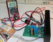
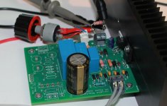
This morning I had the time to test the power supply again and I reduced the length of the cable to the pot from 10 inches to less than 1 inch (about 2 cm) and... Bingo The power supply is now working perfectly with 309 V DC output for 246 V AC from the R-core transformer on the input and 332 V DC after rectifiers (see photos)... I can even increase output voltage up to 325 V DC until the LT3080 has not enough voltage to work correctly ! These tests were done with a 220k load, I will now test the power supply in real conditions with the tube RIAA preampli...
Cheers,
Marc
My idea in the last line of my 4th December post was the good one
This morning I had the time to test the power supply again and I reduced the length of the cable to the pot from 10 inches to less than 1 inch (about 2 cm) and... Bingo
The power supply is now working perfectly with 309 V DC output for 246 V AC from the R-core transformer on the input and 332 V DC after rectifiers (see photos)... I can even increase output voltage up to 325 V DC until the LT3080 has not enough voltage to work correctly ! These tests were done with a 220k load, I will now test the power supply in real conditions with the tube RIAA preampli...Cheers,
Marc
Attachments
How to rid that mains frequency hum?
Hello All,
Hey I am a bit slower with this than I planned. I have access to an AP analyzer for a while.
The first regulator Hooked up is the shunt regulator kit from K&K Audio, for the heater regulator there is a Tent Labs filament regulator.
Hats off to MerlinB.
First off I used the bench high voltage supply and adjusted the 12B4 voltage and current to minimize the valve noise, B+ 156vdc, grid -17vdc. Then the prototype H+ and L+ power supplies were attached to the valve circuit.
The output transformer is a Transendar. The input voltage to the valve grid was adjusted for a measured voltage of 0.114 RMS volts across the 70ohm resistor placed at the output of the transformer. This will be very near 90dB output from the LCD 2 headphones.
See the attached plots.
The prototype supplies with regulators worker out very well.
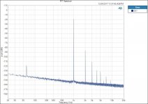
The -120dBV mains 60hz peak plexes me. It just seems to come out of the air and will not go away. If I turn off the heater supply the 60hz peak disappears. Keep in mind -120dBV is 1 PPM, or 0.000001 RMS volts.
I do not recall seeing many or any valve circuit FFT’s where the mains frequency is absent. Many posters append that part of the plot.
DT
Hello All,
Hey I am a bit slower with this than I planned. I have access to an AP analyzer for a while.
The first regulator Hooked up is the shunt regulator kit from K&K Audio, for the heater regulator there is a Tent Labs filament regulator.
Hats off to MerlinB.
First off I used the bench high voltage supply and adjusted the 12B4 voltage and current to minimize the valve noise, B+ 156vdc, grid -17vdc. Then the prototype H+ and L+ power supplies were attached to the valve circuit.
The output transformer is a Transendar. The input voltage to the valve grid was adjusted for a measured voltage of 0.114 RMS volts across the 70ohm resistor placed at the output of the transformer. This will be very near 90dB output from the LCD 2 headphones.
See the attached plots.
The prototype supplies with regulators worker out very well.
The -120dBV mains 60hz peak plexes me. It just seems to come out of the air and will not go away. If I turn off the heater supply the 60hz peak disappears. Keep in mind -120dBV is 1 PPM, or 0.000001 RMS volts.
I do not recall seeing many or any valve circuit FFT’s where the mains frequency is absent. Many posters append that part of the plot.
DT
Attachments
I do not recall seeing many or any valve circuit FFT’s where the mains frequency is absent. Many posters append that part of the plot.
DT
Stereophile is just showing an IMD chart -- which is, of course, very useful. I don't know if the SYS2522 supports IMD.
You can make the 60/120Hz go away by using a linear abscissa!
You say “You can make the 60/120Hz go away by using a linear abscissa!” please tell me more.
DT
Change the sweep from logarithmic to linear.
Maita regulator
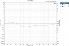
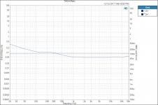
This is the 21st LT3080 Maita regulator.
Looks to be within noise specification.
The same test configuration as above.
I like the looks of the shunt regulator much better.
Old school to follow later.
DT
This is the 21st LT3080 Maita regulator.
Looks to be within noise specification.
The same test configuration as above.
I like the looks of the shunt regulator much better.
Old school to follow later.
DT
Attachments
I was just being facetious wrt the abscissa!
The LT3081 datasheet PSRR vs Frequency chart, @60 Hz @room temperature =~80dB.
Just throwing in this chart of PSRR vs Frequency for various. The Salas shunt is excellent in this regard, but it has some issues with "reverse-PSRR"
The LT3081 datasheet PSRR vs Frequency chart, @60 Hz @room temperature =~80dB.
Just throwing in this chart of PSRR vs Frequency for various. The Salas shunt is excellent in this regard, but it has some issues with "reverse-PSRR"
Attachments
 Jackinnj,
Thank you for posting your chart. I went back and reread your LA power supply bake off article.
The positive voltage half of the Jung/Didden Super Regulator with -120dB rejection at 60Hz may make a good valve heater power supply. I went to the diyAuydio Store and purchased a PCB to give it a try.
Did you plot distortion vs frequency sweeps or FFT’s at the output of the JFet line stage in your power supply bake off, seems like that would be a good place to measure the effects of the various power supplies? Measured effects vs perceived quality would be interesting.
DT
DT -- be very careful using the AP with high voltages -- I inadvertently blew out one of the inputs on mine. Even with cap coupling strange things happen. I now have a "sacrificial" preamp with much higher input impedance than the SYS2722. Noise floor is higher, but of little consequence.
Of course, the folks in Oregon were happy to fix the front end and calibrate the unit and it was back in less than 10 days.
Of course, the folks in Oregon were happy to fix the front end and calibrate the unit and it was back in less than 10 days.
DT -- be very careful using the AP with high voltages --.....
Jackinnj,
Thank you for the friendly caution about the high voltage.
I am also a little leery about poking around inside the HV power supplies. That is one of the reasons I have been looking at power supply noise and distortion at the secondary of the output transformer.
I am sorry to hear about the damage to your analyzer. I have been looking at your SSM2019 measurement amplifier, it makes sense. Do you have an AutoRanger? Jan recently did a GB. Seems like the AR could do a good job of protecting the AP input.
I have a similar sad story. The recently replaced 2522 had to make a trip to see Duke in Los Angles for the same repair. Do you know Duke here on diy, he worked for AP in Beaverton?
DT
Alright, perhaps you fine gentlemen can shed some light on this?
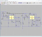
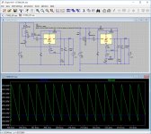
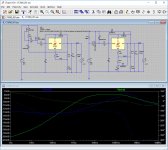
I'm in need of a high voltage low noise power supply with good regulation so I entered the schematic posted in the 1st post in LTspice and ran some transient and AC analysis, however it doesn't appear to work properly as it clearly oscillates (Vout).
I reworked the schematic to something that does seem to work properly (Vout1), I'm just a little puzzled as to why the original shows issues as clearly this has been built and appears to be working as per the replies in this topic?
Attachments
SSM2019 is good for low voltage supplies, but Zin is essentially two 10k resistors. Too low for our purposes.Jackinnj,
I am sorry to hear about the damage to your analyzer. I have been looking at your SSM2019 measurement amplifier, it makes sense.
DT
For the range of AP's we are dealing with, a gain of 10 to 100 is satisfactory, so a low-noise JFET opamp will do. I have one which uses a SPDT switch to ground the input through 10k after the 1uF 630V blocking cap. A little incandescent lamp or 1/16th Amp fuse is helpful too.
For measurement of PSRR, Zout and stability a Jensen line-out transformer can be used. The JT-123-BLCF was discussed in an AP application note, but less expensive units can be found on Ebay. The price of these babies has doubled in the last few years.
This is the 21st LT3080 Maita regulator.
Looks to be within noise specification.
The same test configuration as above.
Thank you for posting the measurements. It's always good to see my circuits in action.
Looks like you're seeing a bunch of rectifier-related hash and IMD products. Did you ever try with a linear frequency sweep as suggested earlier? Did you try to see if you could lower the mains hash? The 21st Century Maida Regulator has 75-80 dB of line regulation, so I'm rather surprised that you see any hash at all. I seem to recall pretty clean spectra in my measurements...
Here's the "before" vs "after" shot from my DG300B amp (400 V @ 225 mA):

How much current does your circuit draw? That will not impact the 21st Century Maida, but it will impact a shunt regulator design.
Tom
Last edited by a moderator:
For measurement of PSRR, Zout and stability a Jensen line-out transformer can be used. The JT-123-BLCF was discussed in an AP application note, but less expensive units can be found on Ebay. The price of these babies has doubled in the last few years.
Should have mentioned that Jensen is pretty useless above 20kHz.
Some better broad-band transformers can only pass a few mA before going pffft.
Hash
Hello,
My space is a mess and it is getting worse. It is all torn up before I make it better. There is more time to do this stuff now.
Jackinnj,
Thank you, I hear your words. Yes I will be measuring power supply variables with an eye on distortion products at the audio amplifier output. I am sure that there are impedance and dampening things going on between an active power supply and amplifier the same as between the amplifier and the speaker/driver. Fun stuff!
Generating Signals with DC on System Two Family Analyzers - Audio Precision
Tom,
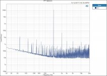
"Hash", that is what it looks like, however most all of it is below 1uv.
The input to the Maita regulator is a Triad N 68X isolation transformer with the secondary winding as input and the primary winding as output. The AC output is ~207 vac. After the rectifier and a string of R C R C R C’s the input to the Matia is a relative smooth 200ish DC volts. The same transformer rectifier and smoothing was used for the K&K shunt regulator. The tube circuit draws about 35ma plus 35ma for the shunt for a total of 70ma for the 12B4A and shunt. For the Maita and 12B4A 35ma total. The Maita regulator had about 200vdc input and 173vdc output, somewhere near 25v delta.
The FFT length was 192K and 20 averages for both the shunt and Maita. The input to the APX was connected across a 70R resistor at the secondary of the Transendar headphone output transformer.
For interest and contrast on a previous day I had a Keysight N5752A bench power supply, connected to a TubeCad linear regulator supplying the same SET 12B4A. At 25vdc delta the hash was remarkably bad. As the bench voltage was increased the hash did not abate until the delta was over 50vdc.
After the bench remodel I will try the adjustable dc supply with the Maita regulator to see what happens to the “hash” as the input dc voltage is adjusted.
Tom,
Please tell me more about "a linear frequency sweep" I will be glad to run it.
DT
Hello,
My space is a mess and it is getting worse. It is all torn up before I make it better. There is more time to do this stuff now.
Jackinnj,
Thank you, I hear your words. Yes I will be measuring power supply variables with an eye on distortion products at the audio amplifier output. I am sure that there are impedance and dampening things going on between an active power supply and amplifier the same as between the amplifier and the speaker/driver. Fun stuff!
Generating Signals with DC on System Two Family Analyzers - Audio Precision
Tom,
"Hash", that is what it looks like, however most all of it is below 1uv.
The input to the Maita regulator is a Triad N 68X isolation transformer with the secondary winding as input and the primary winding as output. The AC output is ~207 vac. After the rectifier and a string of R C R C R C’s the input to the Matia is a relative smooth 200ish DC volts. The same transformer rectifier and smoothing was used for the K&K shunt regulator. The tube circuit draws about 35ma plus 35ma for the shunt for a total of 70ma for the 12B4A and shunt. For the Maita and 12B4A 35ma total. The Maita regulator had about 200vdc input and 173vdc output, somewhere near 25v delta.
The FFT length was 192K and 20 averages for both the shunt and Maita. The input to the APX was connected across a 70R resistor at the secondary of the Transendar headphone output transformer.
For interest and contrast on a previous day I had a Keysight N5752A bench power supply, connected to a TubeCad linear regulator supplying the same SET 12B4A. At 25vdc delta the hash was remarkably bad. As the bench voltage was increased the hash did not abate until the delta was over 50vdc.
After the bench remodel I will try the adjustable dc supply with the Maita regulator to see what happens to the “hash” as the input dc voltage is adjusted.
Tom,
Please tell me more about "a linear frequency sweep" I will be glad to run it.
DT
Gents? I would appreciate getting some feedback on my post. As in the simulator the circuit clearly shows oscillation, hence why this works well in practice has me a little puzzled, unless no one has bothered to find their high voltage oscilloscope probes and actually measured the circuit front to back?
- Status
- This old topic is closed. If you want to reopen this topic, contact a moderator using the "Report Post" button.
- Home
- Amplifiers
- Power Supplies
- LT3080 High Voltage Floating Regulator