“Reverse-PSRR” addresses disturbances caused on the load side of the regulator.
Yes, probably relates to the inadequacies of the error amplifier. The concept was probably developed by the folks in Austria who make the Bode-100, or their co-conspirators at Sandler Associates (Picotest.com)
Here's the application note: https://www.omicron-lab.com/fileadm...e_Transfer/App_Note_Reverse_Transfer_V2_0.pdf
Pretty clever,
jackinnj,
Thanks for the insights and link to more expensive test/measurement equipment. I think of it as load regulation. Omicron Lab calls it Power Supply Reverse Transfer. I will follow your lead and call it Reverse PSRR.
Pretty clever that Jung/Didden Regulator with the boot-strap connection to the pre-regulator ADJ pin. Load side disruptions wrapped around for the pre-regulator to modulate as if the disruptions were on the line side.
DT
@Jack,
That looks like a nice piece of kit, but well outside of anyone's hobby budget if they're just looking to get some PSRR or reverse PSRR measurements done. Besides, any hobbyist worth their salt will come up with a way to do just that, albeit not with the click of a button, it'll involve noting values in a Excel sheet with a function generator being sweeped across a frequency band.
That looks like a nice piece of kit, but well outside of anyone's hobby budget if they're just looking to get some PSRR or reverse PSRR measurements done. Besides, any hobbyist worth their salt will come up with a way to do just that, albeit not with the click of a button, it'll involve noting values in a Excel sheet with a function generator being sweeped across a frequency band.
Hello,
just ordered a Jensen transformer to use per this AP Application Note 106.
https://www.ap.com/download/technot...d=OdI6wVsfFqUNvvRVToTd8RfTB7_emI-4UsmuWQQgc7Y
Looks straight forward to use with APx555.
Not to reinvent the wheel but to get the tools up and functioning.
DT
FYI
To download this AP TN106 you first need to login to the AP site.
In the past, I've injected current for phase margin measurements using a Tektronix CT-6. At $600 it's not exactly cheap. Then again, if you do need to measure the PM, it's pretty handy to have.
As pointed out in the AP tech note, beware of transformer saturation with DC current when measuring PSRR, line rejection, and the like.
That's my philosophy as well.
Tom
As pointed out in the AP tech note, beware of transformer saturation with DC current when measuring PSRR, line rejection, and the like.
Not to reinvent the wheel but to get the tools up and functioning.
That's my philosophy as well.
Tom
Last edited:
The transformer mentioned in the AP Application note is pretty good -- but only to 22kHz.
Having a 2-way conversation w Elvee on this topic.
What we need for testing HV tube supplies
An VNA can be set up as an S-parameter test set without a lot of hassle.
Injecting current galvanically (via CT6)-- I think the operative frequency range should be 10kHz to 10MHz -- that's where the problems seem to surface. You'll need a "normalize" regimen on your VNA to deal with the probe's issues below 250kHz.
Last edited:
I 'd like to ask if the Schema Power supply variable IRFI840 posted earlier in this thread can work as a variable power supply of 50-250 volt at a max 400mA current.
Also, the internal current limiting of the 3080 is enough to protect it in case of a short circuit at the output?
My next step would be to find a way to digitally control the output voltage. Maybe in the place of the pot a current source controlled by a MCU can be used.
Thanks,
Ioannis
Also, the internal current limiting of the 3080 is enough to protect it in case of a short circuit at the output?
My next step would be to find a way to digitally control the output voltage. Maybe in the place of the pot a current source controlled by a MCU can be used.
Thanks,
Ioannis
My next step would be to find a way to digitally control the output voltage. Maybe in the place of the pot a current source controlled by a MCU can be used.
Thanks,
Ioannis
The voltage at the top of the current setting resistor is going to be close to the output voltage.
Since I was very satisfied with my power supply in post 22, I have redesigned a high voltage only version to use in a lab power supply for vacuum tubes test :
I have added the pot on board to keep connection short, and it can be mounted on the front panel with the heatsink in the back.
Rgds,
Marc
I have added the pot on board to keep connection short, and it can be mounted on the front panel with the heatsink in the back.
Rgds,
Marc
Attachments
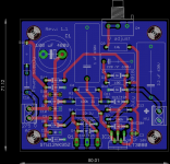
I suppose that your pot is of high voltage one.
The distances in your pcb maybe is not enough for the high voltages. You may need to increase to 3-5 mm
Second all the above.
I would suggest eliminating the output connector -- just two well separated (spaced) solder pads. The connector you illustrate may not be rated for HV.
You can provide a lot of insulation by cutting a slot between ground and HV. You can also put the "+" side traces on one side of the PCB, and those closer to ground potential on the other side.
Thanks for yours feedback.
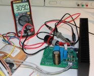
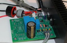
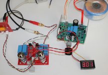
I have not had high voltage problem with the first version of this power supply (see pictures) and I am using similar PCB design rules in Tube amplifiers like the EL34 Baby Huey PCB ( EL34 Baby Huey Amplifier ) which has been sold in qty of nearly 400 pieces without any complaint about voltage problems")
I have already received the PCB for this new version but I didn't had the time to built them I will let you know when they will be assembled !
Rgds,
Marc
I have not had high voltage problem with the first version of this power supply (see pictures) and I am using similar PCB design rules in Tube amplifiers like the EL34 Baby Huey PCB ( EL34 Baby Huey Amplifier ) which has been sold in qty of nearly 400 pieces without any complaint about voltage problems
I have already received the PCB for this new version but I didn't had the time to built them
I will let you know when they will be assembled !Rgds,
Marc
Attachments
I strongly suggest getting rid of that potentiometer. Replace it with a trimpot. You really don't want the user to be tempted to touch the pot as it'll be floating at voltages near the output voltage.
I also second the calls for greater isolation between high voltage traces and ground.
I'd also look up the voltage rating of the input and output terminal blocks. You'll probably find that they're rated for use at 250 V maximum. A 3-terminal version where you skip the middle terminal would allow you to work up to 500 V.
Tom
Last edited:
Hello Tom,
The purpose of this second design is to build one or more high voltage variable lab power supplies for vacuum tube board test like on the picture, this is the reason for the potentiometer, if I used a trimmer it will just be another version of your very nice 21st Century Maida Regulator
The pot is isolated, the case will be fixed to a grounded front panel and I will use a plastic knob to avoid any risk of touching the high voltage... I also decided to use a leaded version of the LT3080 to fix it on the heatsink to take advantage of its thermal protection for the MOSFET like Pete Millett suggest it in his version of the Maida regulator : High Voltage Regulator
The terminal block I am using (not the ones on the picture which came from my junk box) are Phoenix contact rated at 400 V : https://www.mouser.fr/ProductDetail...=sGAEpiMZZMvPvGwLNS6718PaoTt7FM7ciW3NqkEQwDE= and this is enough in my project since I don't intend to use higher voltage (see the input electrolytic capacitors voltage...)
For the PCB layout, I would like to have greater isolation but this will be difficult with today components without making a much bigger board ! You know it also with your very compact SMD regulator board. I have made two layout for the EL34 Baby Huey and EL84 Baby Huey and more than 500 PCB have been ordered ( https://www.diyaudio.com/forums/group-buys/312869-gb-baby-huey-pcb-68.html#post5613136 ), and up to now there was never report of high voltage problem
Rgds,
Marc
Attachments
I thought about creating my own thread but this seemed a sensible option. I'm currently researching HV regulation but will need the design to cope be customisable for say 300mA at 150V, 100mA at 200V and 100mA at 320V. Whereas most HV tube regulators run up to 50-80mA.
There's a Broskie design here: https://www.pearl-hifi.com/06_Lit_A...ers/Broskie_John/HV_Regulator_OP27_IRF820.pdf
There's a Broskie design here: https://www.pearl-hifi.com/06_Lit_A...ers/Broskie_John/HV_Regulator_OP27_IRF820.pdf
- Status
- This old topic is closed. If you want to reopen this topic, contact a moderator using the "Report Post" button.
- Home
- Amplifiers
- Power Supplies
- LT3080 High Voltage Floating Regulator