i have a question, can i use a electrophoresis power supply or this isn't advisable?
* YES
* NO
* MAYBE
* YES BUT .....
* NOT IN YOUR DREAMS
pick one.

Now for a real answer, you tell us what an electrophoresis power supply is, specially what voltage/current it can supply.
Hi,
yes, I must say the specifications
I need a variable 600v - 200mA HV supply.
I was reading a thread about this, but all models are too old or only in USA. Also, I see that some electrophoresis supply doesn't work properly (spikes, etc...).
I can build a power supply, but I don't know any project of any schematic.
Build a PSU with two sections fed from one secondary: cap input (DC out ~1.4 x secondary AC RMS), and choke input (DC out ~0.9 x secondary AC RMS). That gives you two voltage rails. I did this and have approx 200V and approx 300V to play with. You don't need more accuracy than that for playing with valve amps.
Regulated supplies are more difficult to design and build than audio amplifiers! And they introduce complications like reactive output impedance which can mess up the amplifier you are working on.
Regulated supplies are more difficult to design and build than audio amplifiers! And they introduce complications like reactive output impedance which can mess up the amplifier you are working on.
I posted the design using an LT3080 because it's very straightforward and can be built with a minimum of expense. (The LT3080 is $4.40, a 2W 500k pot around $11). You'd probably want to insulate the shaft of the potentiometer.
A bode plot via LTSpice would be a helpful sanity check.
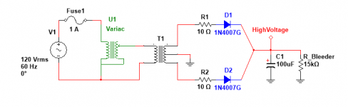
I use a Variac as jazbo8 suggests, but Variacs are pretty expensive outside the US. The great thing about a Variac is that you're not burning a lot of energy in the pass element.
A bode plot via LTSpice would be a helpful sanity check.
I use a Variac as jazbo8 suggests, but Variacs are pretty expensive outside the US. The great thing about a Variac is that you're not burning a lot of energy in the pass element.
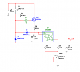
This is a floating variable hv regulator from the new "Art of Electronics" -- the 500k potentiometer controls the voltage from 1 to 450V
Hi.
What's L1 device?
Why FB?
Thanks!
Hi.
What's L1 device?
Why FB?
Thanks!
FB = ferrite bead.
Variac are an autotransformer.Thanks all people for the replies,
I'm newbie and i need a recomendation for variac please. I don't find any variac whit 450 to 600V output.
These usually have taps on the winding at 0, 10%, 90% and max plus the wiper.
This allows wiring in clockwise direction or anticlockwise direction.
The 10% tap is ignored, leaving you with 0, 90% and 100%.
You can wire the mains into 0 and 100% and the wiper taps off any intermediate voltage upto 100% of the mains voltage.
Alternatively you wire the mains to the 0 and 90% and the wiper taps off the intermediate voltage and goes beyond the 90% tap to then give a maximum output of ~110% of the mains voltage.
This is very useful for testing mains powered equipment to the maximum mains supply of 253Vac, here in the UK.
Thanks all people for the replies,
I'm newbie and i need a recomendation for variac please. I don't find any variac whit 450 to 600V output.
That is, put a transformer after the variac to get a higher voltage.You can make a very simple and useful HV supply with just a variac, an industrial PT (say 230V to 480V), a bridge rectifier and some filter caps. You don't really need a regulated PS for testing guitar amps...
Mona
This is a floating variable hv regulator from the new "Art of Electronics" -- the 500k potentiometer controls the voltage from 1 to 450V
I think there is a mistake in this circuit. LND150 should be a CCS, so R1 should be on the source of LND150 and in the place of R1 should be a gate stoper of lets say 1K. Moreover, with values shown useable current out is about 60-70mA max (if my calculations are correct) to increase available current the 20 Ohm resistopr should be decreased and consequently the mosfet pass element to change with something beefier in order to be able to handle the extra power consumed on it.
On a second thought R1=4k7 is just fine as it is at the gate and LND provides 1-2mA constant current, but the max output current is about 70mA as already noted! However, increasing zener voltage (either decreasing the 20 Ohm resistor) allows for higher current and higher wattage consumed on the pass mosfet.
Last edited:
I think there is a mistake in this circuit. LND150 should be a CCS, so R1 should be on the source of LND150 and in the place of R1 should be a gate stoper of lets say 1K. Moreover, with values shown useable current out is about 60-70mA max (if my calculations are correct) to increase available current the 20 Ohm resistopr should be decreased and consequently the mosfet pass element to change with something beefier in order to be able to handle the extra power consumed on it.
The arrow pointing out of the device is the source. For an NMOS however, it should be an "innie" instead of an "outie". The author's CAD convention, I guess.
The 22 ohm resistor limits the charge current into C1. Otherwise, the circuit SHOULD be limited by the internal control in the LT3080.
We should probably move discussion of the LT3080 floating HV regulator to another thread.
For the purpose of the thread initiator here's a simple Variac controlled HV supply. You use a separate transformer for the filaments.
Attachments
We should probably move discussion of the LT3080 floating HV regulator to another thread.
http://www.diyaudio.com/forums/powe...h-voltage-floating-regulator.html#post4701816
- Status
- This old topic is closed. If you want to reopen this topic, contact a moderator using the "Report Post" button.
- Home
- Amplifiers
- Power Supplies
- Variable power supply for tube amps