
This might be of help. LD1084 with ground plain and t bar between main caps. Not bad really. LM317 as good if 2.2 A type. I have a LM324 and BC327 ( ? collector to V+ ) as crow bar to V set. Makes it jump down to 2.5 V ( LM324 + Vce loss X Vref ). Note last graph switched off. Ignore red wrighting. Te scope is set at 1V ref. Add 21.5 dB @ 12V. - 130 db is realistic for preamp use.
Simplified version
An externally hosted image should be here but it was not working when we last tested it.
Is this one you have designed and built yourself ?
Hi Mooly,
No this one is from ebay.
Here is the link
LM317 350 LT1083 1085 LOW Noise Adjustable Linear Regulated Power PCB Soft Star | eBay
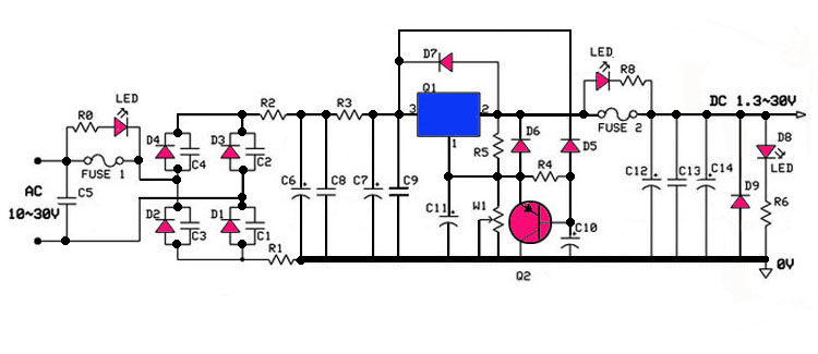
And I have some serious reservations against this circuit. However I did buy 4 boards to modify and use instead.
My reservations are mainly on the series resistors R1, R2 ad R3. They are supposed to be current limiting?
But the value like R3, if we use 2.2A current 5W is dropped across the resistor. But why?
Thanks.
So it appears yunwt might just have been trying to promote these.
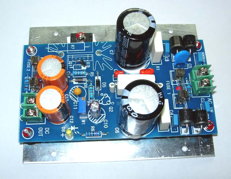
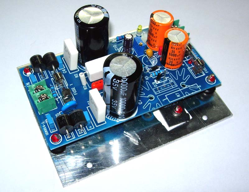
Must be. But the boards are pretty decent. I am using them for building my own regulator boards. Saves time for $4 what I paid including shipping. Whoever was selling it, shipped me quite fast. I got 4pcs today!
My reservations are mainly on the series resistors R1, R2 ad R3. They are supposed to be current limiting?
But the value like R3, if we use 2.2A current 5W is dropped across the resistor. But why?
Just reading through the notes and it seems that R3 can be in the 0.1 to 10 ohm range. I guess that leaves it up to the user to decide the most appropriate values.
Just ordered 1 pcb do I get the schema and BoM with it?
Schematic is only that is shown in the listing. And No I did not get a BOM or schematic with the boards.
I see an issue with the design.
The output fuse will drop voltage. Therfore it should be within the sense loop. Otherwise you will have poor load regulation.
However most IC regulators are well protected against shorts and over current. the output fuse is not necessary. I would just bypass it with #14 wire.
The output fuse will drop voltage. Therfore it should be within the sense loop. Otherwise you will have poor load regulation.
However most IC regulators are well protected against shorts and over current. the output fuse is not necessary. I would just bypass it with #14 wire.
- Status
- This old topic is closed. If you want to reopen this topic, contact a moderator using the "Report Post" button.
- Home
- Amplifiers
- Power Supplies
- Linear regulator (LT1084,LT1083,LM338, )