Hello all
I’m hoping to get some help on a project I’m looking at doing. I want to build a bench power supply for my LAB that will provide a variable DC supply at about 100mA from a 240v ac supply from my bench isolation transformer.
The reason for this supply is to test valve amp projects before building the final circuit. I wanted the supply to be variable from about 10v to the full 300v dc.
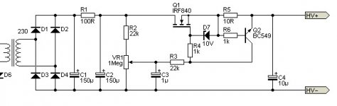
I have already constructed one design attached in image 1 below which for voltage control from 0v to 300v worked very well. However I have found that the output voltage can swing high when switching on as it is unregulated. I tried the circuit powering a heater element at 45vdc and when switching it on the voltage spiked to 55vdc then back down again. This destroyed the valve filament.
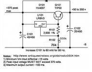
I am looking at the other circuit in image 2 which is a regulated supply. Has anyone built this and is it stable. What sort of output current could I get from this circuit.
I have an idea to build the first unregulated circuit for the plate voltages as this can be fairly unregulated, and then the second circuit for the heater elements at a lower input voltage about 80v ac.
Any help would be much appreciated I am a newbie to this I have experience with HV circuitry but not with designing the circuit.
I’m hoping to get some help on a project I’m looking at doing. I want to build a bench power supply for my LAB that will provide a variable DC supply at about 100mA from a 240v ac supply from my bench isolation transformer.
The reason for this supply is to test valve amp projects before building the final circuit. I wanted the supply to be variable from about 10v to the full 300v dc.
I have already constructed one design attached in image 1 below which for voltage control from 0v to 300v worked very well. However I have found that the output voltage can swing high when switching on as it is unregulated. I tried the circuit powering a heater element at 45vdc and when switching it on the voltage spiked to 55vdc then back down again. This destroyed the valve filament.
I am looking at the other circuit in image 2 which is a regulated supply. Has anyone built this and is it stable. What sort of output current could I get from this circuit.
I have an idea to build the first unregulated circuit for the plate voltages as this can be fairly unregulated, and then the second circuit for the heater elements at a lower input voltage about 80v ac.
Any help would be much appreciated I am a newbie to this I have experience with HV circuitry but not with designing the circuit.
Attachments
Have a look at the following forum
http://forum.allaboutcircuits.com/threads/hv-valve-bench-power-supply.117452/#post-922143
i started this to get other views. Its progressing I have a variable power supply from 0-300 VDC but not yet regulated
http://forum.allaboutcircuits.com/threads/hv-valve-bench-power-supply.117452/#post-922143
i started this to get other views. Its progressing I have a variable power supply from 0-300 VDC but not yet regulated
Designing and building a high voltage regulated power supply so it is safe and reliable is significantly harder than designing basic audio equipment. I would not start from here.
Instead, build a PSU which provides both a cap input PSU and a choke input PSU from the same secondary. That way you get two voltages, which can cover most common needs. I did 200V and 300V (nominal). Few valve circuits need regulated voltage rails.
Instead, build a PSU which provides both a cap input PSU and a choke input PSU from the same secondary. That way you get two voltages, which can cover most common needs. I did 200V and 300V (nominal). Few valve circuits need regulated voltage rails.
Maybe start with a proven design? You can find them in the ARRL handbook, or look here: Heathkit Schematic and Manual Archive | Vintage Radio Info
Find the IP-17 - a regulated HV Power Supply comeplete with meters. You can find these on ebay, of course, but I'd bring it up slowly and make sure caps are okay. I have one, it is an outstanding addition to my bench.
Find the IP-17 - a regulated HV Power Supply comeplete with meters. You can find these on ebay, of course, but I'd bring it up slowly and make sure caps are okay. I have one, it is an outstanding addition to my bench.
Thanks for the link this will be a good one to keep. The power supply on this is tube based. i have seen these and thought about doing it this way but for a bench power supply and for cost purposes i would prefer a solid state regulation. I have found on ebay a solid state variable power supply which i am considering link below
HV400 Variable High Voltage Power Voltage Regulator DIY Kit 50-300V 0.3A 30V 2A | eBay
There is also a design in a magazine but i would need to get hold of this
https://www.elektormagazine.com/magazine/elektor-200704/18496
HV400 Variable High Voltage Power Voltage Regulator DIY Kit 50-300V 0.3A 30V 2A | eBay
There is also a design in a magazine but i would need to get hold of this
https://www.elektormagazine.com/magazine/elektor-200704/18496
Steve, if you're just looking for a circuit board, also consider those from John Broskie:
New Low-Voltage and High-Voltage Regulator Kits
FWIW, I've bought PS boards from John over several years. They are TOP quality and I can highly recommend them.
The ebay one you linked only goes to 300v which might be good for your needs, but I often wish mine (which goes to 400v) would be good to 450v or so. Also, consider if you might want to include a B- supply, again, very helpful.
Thanks smbrown.
I have had a look at this site. it was recommended by some one. i might end up using them if i cannot find an alternative Europe UK supplier.
I known what you mean about the higher voltages for the plate but i need to start somewhere. the one from ebay can supply all values from 0-300 VDC which is pretty impressive
Instead of trying to build something i just reconditioned a Heathkit IP-2717A, works great for mocking up tube amp builds, but you do need to have your head screwed on when using it as it could bite you.
Main transformer can be re-configured for 240v mains too so it will work this side of the pond.
Regulated High Voltage Power Sup IP-2717 Power-S Heathkit Br
http://www.google.ie/url?sa=i&source=imgres&cd=&ved=0CAYQjBwwAGoVChMIq4i0g_CXyQIVw5APCh2RZgI0&url=http%3A%2F%2Fwww.mhzelectronics.com%2Febay%2Fbrent2%2FHeathkit_IP-2717A_High_Voltage_Power_Supply_2.jpg&psig=AFQjCNHsAYbSd9tbvT0E-SKTayRAUp5FFw&ust=1447864048146774
Why not keep it exceedingly simple?
A nice high voltage transformer (>350v) with a small dedicated variac (saw a couple very cheap on ebay).
This will allow a very incremental increase in anode voltage. Very useful to troubleshoot circuitry.
If not, go with the Tinkerbox series from Edcor. Again a dedicated variac would help keep the voltage rise (and spikes) in check https://www.edcorusa.com/tbpwr-hv-1
Why not keep it exceedingly simple?
A nice high voltage transformer (>350v) with a small dedicated variac (saw a couple very cheap on ebay).
This will allow a very incremental increase in anode voltage. Very useful to troubleshoot circuitry.
If not, go with the Tinkerbox series from Edcor. Again a dedicated variac would help keep the voltage rise (and spikes) in check https://www.edcorusa.com/tbpwr-hv-1
I would go with the Variac and transformer approach, I have a few HV transformers 500 and 900 V with 110V primaries which is a bit of a problem here in EU. The Variac would allow all possibilities including over driving for short periods to allow tests to be carried out.
I have used several bench supplies over the years. One of the most useful supplies I ever made was very simple. it contained three variacs, three industrial control transformers, and three solid state rectifier - filter combinations. This made three separate "power supplies" in a single, very heavy cabinet.
PS #1 was for heaters and filaments. It used a variac feeding a control transformer that had two 12 volt 10 amp secondaries. Each secondary had its own output jacks. they could be used independently, wired in series for 0 to about 28 volts at 10 amps, or wired in parallel for 0 to 14 volts at 20 amps. I could jumper them to a rectifier - filter board for 0 to about 36 volts DC.
PS #2 and PS #3 were identical. they used a variac feeding an industrial transformer that delivered 240 volts AC at 1 amp (250 VA). It fed a bridge rectifier - filter board to provide 0 to about 325 volts depending on load. There were two of these supplies that could used independently (for circlotrons) or wired in series for 0 to 650 volts.
These were not regulated power supplies but did represent what was often found in commercial tube amps. I used this power supply for about 10 years before eventually swapping it out for the collection of surplus Fluke and HP gear that I have now.
My biggest power supply currently is a surplus HP 6448B that will go up to 650 volts and 1.7 amps. I have actually designed a couple of amps that could use MORE POWER, however this unit is at the limit of a US spec power outlet, so that is where I stopped. That tube amp made 525 watts.
I have moved and now have 240 volts and up to 50 amps available, so I will be building a bigger power supply in the future, but I have to build a new lab first.


You dont really have to, that capacitor is there to direct AC from the main output bus, its a high pass filter, that is not too critical to the functioning of the circuit. 47n-470nF will work OK.
Furthermore you can get a lot better gain by putting the error tube 6SJ7 in pentode instead of triode strapping it. for that the output divider with two 10K 3W resistors will suffice.
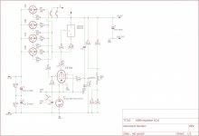
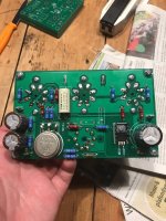
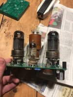
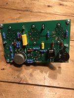
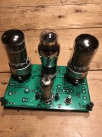
Here are photo's of a supply i built using two 6080/6AS7G tubes, VR150 reference(0D3) and EF184.
Theres a bit of theory behind these kind of supplies, ideally you want the EF184 to have a lot of gain, so it can counteract the ripple more effectively. I solved this with a 10M45S current source, if you load a pentode with a current source, you increase the gain by quite a bit. (Up to ten times last time i did some calculations)
If you want i have a few PCB's for this project leftover, they have one little error but are usable.
Furthermore you can get a lot better gain by putting the error tube 6SJ7 in pentode instead of triode strapping it. for that the output divider with two 10K 3W resistors will suffice.
Here are photo's of a supply i built using two 6080/6AS7G tubes, VR150 reference(0D3) and EF184.
Theres a bit of theory behind these kind of supplies, ideally you want the EF184 to have a lot of gain, so it can counteract the ripple more effectively. I solved this with a 10M45S current source, if you load a pentode with a current source, you increase the gain by quite a bit. (Up to ten times last time i did some calculations)
If you want i have a few PCB's for this project leftover, they have one little error but are usable.
Attachments
Last edited:

....if you load a pentode with a current source, you increase the gain by quite a bit.....
Oddly, the plan in #17 seems to run a pentode as a triode, leaving a lot of gain un-used.
Last edited:
- Home
- Amplifiers
- Power Supplies
- HV Tube bench power supply