Hi,
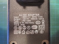
I found the PSU seen on the attachment, FW 1299, made by Friwo. It is a 12VDC linear (low noise?) PSU using a CA723 IC and a 2N6121 power transistor. There is a trim pot for output voltage adjustment but seems not working. I googled and found a lot of schematics but not something very close to that. I emailed to Friwo for a schematic and they answer me that: ...we cannot submit you the schematic you asked for. This is due to the fact that we have phased out production of our type FW1299 - in fact we do not produce linear power supplies any more. This decision has been made by our General Management more than 10 years ago and consequently, no technical records have been kept of linear units since production of this technology has been stopped.
Would anybody help with the schematic?
Attachments
do you want to copy it or fix it?
No, I want to modify it, I tried a reverse engineering but my eyes did not help me that much...
Hi,
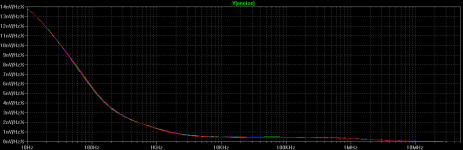
I forgot to mention the forum that finally I reached somewhere by reverse engineering. I found that Inv pin4 and Comp pin13 of the 723 are connected via a 100n cap. Nowhere found any info about the size of this cap. I run a LTspice sim and found that the psu output noise depends very much to the size of that cap. Since the psu powers an RF amp any info welcome.
I forgot to mention the forum that finally I reached somewhere by reverse engineering. I found that Inv pin4 and Comp pin13 of the 723 are connected via a 100n cap. Nowhere found any info about the size of this cap. I run a LTspice sim and found that the psu output noise depends very much to the size of that cap. Since the psu powers an RF amp any info welcome.
Hi,
I forgot to mention the forum that finally I reached somewhere by reverse engineering. I found that Inv pin4 and Comp pin13 of the 723 are connected via a 100n cap. Nowhere found any info about the size of this cap. I run a LTspice sim and found that the psu output noise depends very much to the size of that cap. Since the psu powers an RF amp any info welcome.
That cap helps to "slow down" the feedback loop and hence avoiding ringing
That cap helps to "slow down" the feedback loop and hence avoiding ringing
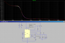
Change 100n to 1000n I got the attached from the sim. Is it better or overkill?
Attachments
Change 100n to 1000n I got the attached from the sim. Is it better or overkill?
No true answer as it depends on your application. I won't change the suggested 100n value though. Too high a value and the regulator doesn't react fast enough to changes in load.
You would want to the simulate output impedance vs frequency, while using different values of that cap.
Last edited:
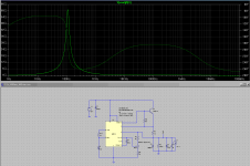
I run a sim with no load (R2=100G) and there is a peak at ~100Hz, see the plot.
Is the above sim correct?
Looks correct to me. That is with 1000nF for compensating capacitor I presume?
The regulator stops being a regulator at 100Hz. Although Z_out already rises to >1ohm at 10Hz. This is unacceptable for a regulator.
Stick to 100nF and you should see the peak shift to 1000Hz.
Your noise simulation may show less noise with a bigger capacitor. However this is only for noise generated by the regulator itself, and does not include how well the regulator suppresses noise coming from the load. High output impedance means noise at the load stays at the load instead of being eaten by the regulator.
That is with 1000nF for compensating capacitor I presume?
Wrong! If you look at my post #9 pic the cap is 100n.
When cap value increases the peak goes down to frequency if decreases the peak goes up to frequency. The value of 100n goes the peak at ~100Hz (2x50Hz main freq) may be this done intensionally by the designer of the psu.
The amp loads the psu by ~200ma current at 12VDC, ie a ~60ohms load, then the source psu impedance is less than 0.5ohms in the sim.
Last edited:
I have started this thread in order to modify the psu (after I realized the circuit) for minimum noise at its output, that's why I presented some sims to study its behavior, although I'm not good to ltspice sims. If you're interested in looking at the design and offering insight to where I've got errors, etc, by all means please do.
an LNA with bandpass filtering.
Yes, but to measure the noise vs frequency I need a SA which is out of the question. Is there any suitable SW?
Yes, but to measure the noise vs frequency I need a SA which is out of the question. Is there any suitable SW?
AC couple the output to a scope (peak measurement) or AC voltmeter (average measurement) and read the noise voltage.
- Status
- This old topic is closed. If you want to reopen this topic, contact a moderator using the "Report Post" button.
- Home
- Amplifiers
- Power Supplies
- 12VDC Linear PSU