The short answer is: I don't know because I haven't tried this. And I'm surprised to hear that output transformers have multiple primaries or multiple secondaries, so that it's important to get the phase dots correct.will the tester work with output transformers ? (tube amps)
The long answer is: it depends on the impedance of the primary at the test frequency (150 Hz). Referring to the schematic, which is Fig2 of post#1 in this thread, a series circuit is formed. The oscillator chip's output at pin 3, drives (R6 in series with R7) in series with the impedance of the transformer primary. If the transformer primary's impedance at 150 Hz is very low compared to 136 ohms, then the signal across the primary (node W1) is very small. Because it's a step-down transformer, the signal across the secondary (node W2) will be even smaller. It might be too small for the phase detector to detect ... and the tester's output will be unreliable.
Also, if the primary impedance at 150 Hz is very low, the series network to ground will conduct lots of current. In the worst case, 9V/(68R+68R) = 66 milliamps. The resistors are dissipating 0.6 watts (!!) and will get very warm.
There are a few options available to you:
- Forget about the PhaseDots tester and just use a scope and a signal generator instead.
- If the cost of a PhaseDots tester is so low that you wouldn't be upset if it doesn't work with your transformers, then buy it and try it.
- Unlike 50 Hz mains transformers, output transformers are designed to work well at 8 kilohertz. So modify a PhaseDots tester's oscillator to run at 8kHz (i.e. decrease capacitor C9). The primary's impedance will be 53X higher at 8kHz than at 150Hz, and the probability of getting good results from PhaseDots will increase by a factor of 53X.
- Look up the datasheets of a few output transformers, which you consider to be representative of the sorts of transformers you might want to connect to PhaseDots some day in the future. What's the impedance of the primary at 150Hz? If it's higher than, oh let's just say, 120 ohms, this gives you confidence that PhaseDots should operate correctly with these.
Last edited:
I took my own advice and looked up a few datasheets. Beware! I am not a tube guy so I looked up tube output transformers whose name I have heard: Hammond. I don't have any idea whether these are well-loved, or vituperatively despised, by diyAudio Tube aficionados. Nor do I have a clue whether they are comparatively cheap or wildly overpriced. Hammond is the only name I knew, so that is the transformer website I visited just now.Hi Mark will the tester work with output transformers ? (tube amps)
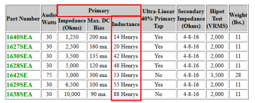
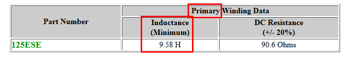
And what I found there was very good news! The impedance of the primary of these Hammond output transformers, is nice and high! Plenty high enough for the PhaseDots tester to drive (and sense!) big signals whose phase is easy to detect. Good news. To calculate the impedance at "f" Hertz, we recall that Z = (2 * PI * f) * inductance. For the Hammond output transformers shown in the attachments,
- 1638SEA (L = 88H) primary impedance Z = 83 Kohms
- 1640SEA (L = 14H) primary impedance Z = 13 Kohms
- 125ESE (L = 9.5H) primary impedance Z = 9 Kohms
All of these have a primary impedance at 150 Hz much much greater than 120 ohms, so PhaseDots will test them just fine.
_
Attachments
Perhaps the easiest way to do that is to change timing capacitor C9. (Schematic and PCB layout shown in post #1). It's on the outer perimeter of the board so there's plenty of room to install a socket, and allow even the clumsiest people with the fattest fingers, to change capacitors at will. I recommend DigiKey part# 1212-1090-ND -- treat it as a breakaway duo plus a spare, and make yourself a two-terminal socket out of two one-terminal sockets. Other readers may offer up alternative part#s at other distributors such as Mouser, Farnell, Maplin, etc. Me, I tend to buy from DigiKey.
When testing 50Hz mains "power transformers" you might not want a high frequency oscillator.
When testing 50Hz mains "power transformers" you might not want a high frequency oscillator.
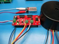
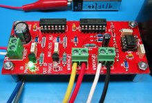
Received it, assembled it, used it. Had to try it over and over because it was so much fun. Works like a charm!!! No "magic blue smoke / possible death" cold sweats. I absolutely love this! I don't know why anyone would build the fancy power supply when a 9v battery works great. Now I've got to find some more mystery transformers!!! If y'all have mystery transformers, stick $13 dollars in an envelope and mail it. With croc clip leads hooked to it, it is so easy. Thank you so much!!! A Quasimodo that had leds that lit up when you minimized ringing would be cool.
Last edited:
Marsupialx, if you happen to have a two channel oscilloscope, I think you might enjoy looking at various signals inside the PhaseDots circuit (with a transformer attached). Display the nodes from oscillator output to phase detector input and observe how the circuit actually works. It's so simple that it embarrasses me! Are the waveforms right side up, or upside down? Light up the red LED or light up the green LED. Shockingly easy.
have to agree with marsupial, this is an extremely handy tool to have.
I have been using mine to get some old output transformers marked for correct phasing.
After they sit for 30-50 years in an amp or organ all the wires become the same dull grey color. Now I need to put this in a box to protect it from my carelessness.
I have been using mine to get some old output transformers marked for correct phasing.
After they sit for 30-50 years in an amp or organ all the wires become the same dull grey color. Now I need to put this in a box to protect it from my carelessness.
another good practical video to learn from...https://www.youtube.com/watch?v=Yzo3A-NywSs
If anybody wants to design a PhaseDots Mk.II board, I offer the mild suggestion that a 75 cent, 8 pin microcontroller (with on-chip 1% clock oscillator) might be a good chip to use. You can have it stimulate winding#1 at different frequencies, and then measure at a frequency which gives acceptable waveshapes at winding#2. Now you don't need to worry about tradeoffs between measurement frequency and (L/R) timeconstants; the software+hardware adapts to whatever is connected. You can also test high frequency SMPS transformers as well as 50/60Hz mains transformers. And you can use much more sophisticated phase detectors than a simple XOR. All of this comes at no extra cost, except perhaps the derisive scorn of "old skool" people who think an oscilloscope or a dim bulb tester is the only legitimate and manly way to discover the phase dots of transformer windings.
another good practical video to learn from...https://www.youtube.com/watch?v=Yzo3A-NywSs
thanks that was a good one
Great job BK, congratulations!
I often use masking tape + Sharpie marker to label the wires after determining the PhaseDots. Then I don't have to remember which is which, or remember where I wrote down which is which.
Sometimes I'll also use a ziptie or a piece of cotton string, to gather together the wires of "Winding #N" into a bundle. It's helpful if you do your PhaseDots testing in June but don't actually assemble the PSU until September. Another countermeasure against unreliable human memory. The ziptie / string can be cut away and discarded during assembly, probably right at the moment you're twisting the wires together.
Very slick little tool there Mark. Nicely done.  I have lots of Antek trafos with missing dot info on the wires. I now have an o-scope but, where's the fun in that? O-scopes come with a 1kHz 5v square wave test generator for compensation cal that comes in useful if you don't have a function generator - except I wonder how well it works on 60Hz trafos?
I have lots of Antek trafos with missing dot info on the wires. I now have an o-scope but, where's the fun in that? O-scopes come with a 1kHz 5v square wave test generator for compensation cal that comes in useful if you don't have a function generator - except I wonder how well it works on 60Hz trafos?- Home
- Amplifiers
- Power Supplies
- A little tester to determine transformer PhaseDots with no scope or signal generator